LCD-Monitor Chassis : LS19MYN Model : 943NW / 943NWX SERVICE TFT-LCD Monitor Manual Contens 1. Precautions 2. Product specifications 3. Disassembly and Reassemble 4. Troubleshooting 5. Exploded View & Part List 6. Wiring Diagram 7. Schematic Diagram 943NW / 943NWX Refer to the service manual in the GSPN (see the rear cover) for the more information.
Contents 1. Precautions............................................................................................................... 1-1 1-1. Safety Precautions.......................................................................................................... 1-1 1-2. Servicing Precautions...................................................................................................... 1-2 1-3. Static Electricity Precautions.......................................................................
GSPN (Global Service Partner Network) Area Web Site North America http://service.samsungportal.com Latin America http://latin.samsungportal.com CIS http://cis.samsungportal.com Europe http://europe.samsungportal.com China http://china.samsungportal.com Asia http://asia.samsungportal.com Mideast & Africa http://mea.samsungportal.com This Service Manual is a property of Samsung Electronics Co.,Ltd.
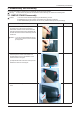
3. Disassembly and Assembly 3. Disassembly and Assembly This section describes the disassembly and reassembly sequences for this monitor. Warning: As this monitor has parts that are sensitive to static electricity, be careful when handling them. 3-1. SIMPLE STAND Disassembly Caution: 1. Turn the monitor off before beginning the disassembly process. 2. Disassemble the monitor carefully as directed in the following procedures. 3.
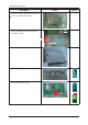
3. Disassembly and Assembly Description Photo Screws 4. Remove the SHIELD-LAMP using the provided JIG. Caution: The SHIELD-LAMP is sharp. 5. Remove the LVDS, LAMP wire, FUNCTION cable, and SPEAKER cable, and then remove the SHIELD-COVER. LVDS LAMP WIRE FUNCTION 6. Remove the LCD panel.. 7. Remove the four (4) screws shown in the figure. 8. Remove the four (4) screws shown in the figure and remove the Bracket support.
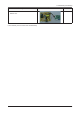
3. Disassembly and Assembly Description Photo Screws 9. Remove the main PCB and IP boards from the SHIELD-cover. ※ The assembly is in the reverse order of disassembly.
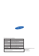
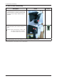
3. Disassembly and Assembly 3-2. HAS STAND Disassembly Description Photo 1. If the Stopper PIN at the back of the stand is not removed, place a soft cloth on the table and place the monitor on it, and then hold the monitor set and remove the Stopper PIN at the back of the stand. 2. T urn the monitor over. Remove the two (2) screws that hold the stand in place and then remove the stand. Caution: W hen removing the screws, hold the stand body with one hand so that the stand does not fall. 3.
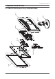
5. Exploded View & Part List 5. Exploded View & Part List M0027 BN63-03965A T0514 M0081 T0003 M0081 M0215 M0174 M0006 M0003 M0013 5-1.
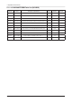
5. Exploded View & Part List 5-1-1. LS19MYNKFZ/XBM Parts List (943NWX) Location No. Code No. Description & Specification Q’ty SA/SNA T0003 BN96-07592B ASSY COVER P-FRONT;[Mckinley]LS19MYW,ABS 1 S.A M0215 BN07-00462A LCD-PANEL;M190A1-L07 1 S.A M0174 BN44-00121K IP BOARD;PWI1904SJ(J),MCKINLEY 943NW/BW, 1 S.A M0081 6003-000115 SCREW-TAPTITE;BH,+,B,M3,L6,ZPC(BLK),SWRC 2 S.A M0081 6003-001439 SCREW-TAPTITE;BH,+,-,S,M4,L8,ZPC(WHT),SW 1 S.N.
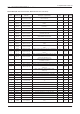
5. Exploded View & Part List 5-2. LS19MYNKFZ/XBM Parts List Service Bom (SA: SERVICE AVAILABLE, SNA: SERVICE NOT AVAILABLE) Level Location No. Code No. Description & Specification LS19MYNKFZ/XBM 943NWX,SAL1/S19B8-LMY,19,LCDMO,ECUADOR Q’ty SA/SNA Remark 0.1 M0002 BN90-01584A ASSY COVER REAR;LS19MYNKBZ/XSF,CMO PANEL 1 S.N.A ..2 M0013 BN96-06380N ASSY COVER P-REAR;LS19MYN,HIPS HB,BK26,S 1 S.A ...3 M0113 BN61-01581A BRACKET-VESA;BI17/19BS,SECC,T1.0 2 S.N.A ...
5. Exploded View & Part List ......6 PCB BN41-00947A 0.1 M0112 ..2 PCB SUB-FUNCITION;Mckinley function,FR-4 1 S.N.A BN91-01877A ASSY SHIELD;MCKINLEY 19,LS19MYW 1 S.N.A BN63-03965A SHIELD-LAMP;943BW/NW,SPTE,T0.3,(Wide) 1 S.N.A 0.1 M0107 BN91-02069A ASSY LCD-CTZ;LS19MYN* 1 S.N.A ..2 M0215 BN07-00462A LCD-PANEL;M190A1-L07 1 S.A 0.1 M0017 BN91-02070A ASSY CHASSIS-CTZ;LS19MYNKB/XSF 1 S.N.A ..2 M0081 6003-000115 SCREW-TAPTITE;BH,+,B,M3,L6,ZPC(BLK),SW RC 2 S.A ..
5. Exploded View & Part List ....4 Q205 0501-002080 TR-SMALL SIGNAL;2SC2412K,NPN,200mW,S C-59 1 S.A ....4 Q207 0501-002080 TR-SMALL SIGNAL;2SC2412K,NPN,200mW,S C-59 1 S.A ....4 Q409 0505-001165 FET-SILICON;SI3443BDV,P,-20V,+-4.4A,65mo 1 S.A ....4 IC112 1103-001410 IC-EEPROM;S-24CS08AFJ-TB1GE,8Kbit,1Kx8, 1 S.A ....4 T0087 1203-003695 IC-POSI.FIXED REG.;NCP1117ST33T3G,SOT22 1 S.A ....4 T0087 1203-003696 IC-POSI.FIXED REG.;NCP1117DT18T5G,DPA K,3 1 S.A ....
5. Exploded View & Part List ....4 R110 2007-000090 R-CHIP;10Kohm,5%,1/10W,TP,1608 1 S.A ....4 R110 2007-000090 R-CHIP;10Kohm,5%,1/10W,TP,1608 1 S.A ....4 R110 2007-000090 R-CHIP;10Kohm,5%,1/10W,TP,1608 1 S.A ....4 R110 2007-000090 R-CHIP;10Kohm,5%,1/10W,TP,1608 1 S.A ....4 R110 2007-000102 R-CHIP;100Kohm,5%,1/10W,TP,1608 1 S.A ....4 R110 2007-000124 R-CHIP;2.2Kohm,5%,1/10W,TP,1608 1 S.A ....4 R110 2007-000309 R-CHIP;10ohm,5%,1/10W,TP,1608 1 S.A ....
5. Exploded View & Part List ....4 C120 2203-005005 C-CER,CHIP;100nF,10%,16V,X7R,1608 1 S.A ....4 C120 2203-005005 C-CER,CHIP;100nF,10%,16V,X7R,1608 1 S.A ....4 C120 2203-005005 C-CER,CHIP;100nF,10%,16V,X7R,1608 1 S.A ....4 C120 2203-005005 C-CER,CHIP;100nF,10%,16V,X7R,1608 1 S.A ....4 C120 2203-005005 C-CER,CHIP;100nF,10%,16V,X7R,1608 1 S.A ....4 C120 2203-005005 C-CER,CHIP;100nF,10%,16V,X7R,1608 1 S.A ....4 C120 2203-005005 C-CER,CHIP;100nF,10%,16V,X7R,1608 1 S.
5. Exploded View & Part List ..2 T0376 6902-000379 BAG AIR;LDPE,T0.2,W1000,L1800,TRP,-,-- 0.001 S.N.A ..2 T0003 6902-000604 BAG WRAPPING;LDPE,T0.02,W500,L10000,T RP, 0.79 S.N.A ..2 M0081 6902-000609 BAG ROLL;LDPE,T0.05,W2400,L1000,TRP,-,- 0.017 S.N.A 0.1 M0019 BN92-03163N ASSY LABEL;LS17MYAKB/XAZ 1 S.N.A 0.1 M0003 BN92-03351E ASSY BOX;LS19MYNKFZ/XBM 1 S.N.A BN69-02296A BOX-02,MONITOR;943NWX-Simple,CB,SY01,A1 1.02 S.N.A ..2 0.
1. Precautions 1. Precautions 1-1. Safety Precautions Follow these safety, servicing and ESD precautions to prevent damage and to protect against potential hazards such as electrical shock. 1-1-1. Warnings 1. For continued safety, do not attempt to modify the circuit board. 2. Disconnect the AC power and DC power jack before servicing. 1-1-2. Servicing the LCD Monitor 1. When servicing the LCD Monitor, Disconnect the AC line cord from the AC outlet. 2.
1. Precautions 1-2. Servicing Precautions WARNING: Caution: Note: An electrolytic capacitor installed with the wrong polarity might explode. Before servicing units covered by this service manual, read and follow the Safety Precautions section of this manual. If unforeseen circumstances create conflict between the following servicing precautions and any of the safety precautions, always follow the safety precautions. 1-2-1 General Servicing Precautions 1.
1. Precautions 1-4. Installation Precautions 1. For safety reasons, more than two people are required for carrying the product. 2. Keep the power cord away from any heat emitting devices, as a melted covering may cause fire or electric shock. 3. Do not place the product in areas with poor ventilation such as a bookshelf or closet. The increased internal temperature may cause fire. 4. Bend the external antenna cable when connecting it to the product.
1.
2. Product specifications 2. Product specifications 2-1. Feature & Specifications Model 943NW / 943NWX Feature � Panel Specifications: 300 cd/m2, 5 ms, CR 1000:1, 170/160 (CR>10) � DPMS : <1W � TCO’03 � Off-Timer function for reducing standby power usages � Windows Vista authentication � Picture;a screen size desire � Supported Color Effect: Black and white/Sepia/Aqua/Green Specifications Item LCD Panel Description TFT-LCD panel, RGB vertical stripe, normally white transmissive, 19” wide Viewable 0.
2. Product specifications 2-2.
2. Product specifications 2-3. Accessories Product Description Ccde. No Quick Setup Guide BH68-00376L Warranty Card (Not available in all locations) BH68-00633B User’s Guide, Monitor Driver, Natural Color Pro Software BN59-00585A D-Sub(15 Pin) Cable BN39-00244G Power Cord 3903-000082 Remark Samsung Electronics Service center 2-4. Accessories (Sold separately) Product Description Ccde.
2.
7. Schematic Diagram 7. Schematic Diagram 7-1. Circuit Descriptions Location Scaler IC200 Flash Memory IC201 Function Remark Besides the ADC, LVDS, and scaling part, an MCU is embedded as well. All of them are integrated into one chip. SE556M-LF Stores the MCU program embedded in the scaler. It is of a flash type and rewritable. MX25LV512 IC203 Stores the OSD and various timing values.
7. Schematic Diagram 7-2. Schematic Diagrams (Scaler Part) SE717M-LF (PC)ANALOG R G B HSYNC VSYNC Display Processing Engine 8Bit LVDS Panel Interface Interface Engine Clock Generator OSD P A N E L MCU +5 ISP 14.318MHz XTAL 3.3V Regulator +5 Function Key 1MB Flash 24C08 EEPROM 1.8V Regulator +5 Inverter 7-3. Schematic Diagrams (Power Flowchart) 5V Panel IP IP Board Board 5V IC 601 (NCP1117ST33T3G) IC 602 (NCP1117DT1815G) 7-2 3.3V IC 201 (MX25L1005MC) 3.3V IC 203 (AT24C08) 3.3V 1.
7. Schematic Diagram 7-4.
7.
GND_4 5.6V ZD104 AGND ZD105 5.6V C3 A2 C4 D109 100OHM R120 4.7NF C112 AGND OUT VSYNC OUT CHK_DSUB OUT BLU+ OUT HSYNC RED+ GRNSOG GRN+ BLU- OUT DDC_SDA_VGA OUT DDC_SCL_VGA OUT REDOUT OUT OUT OUT OUT SDR3.3 +3.3V AVDC3.3 1 IN MGND1 2 AGND C630 100NF 16V GND OUT 3 OUT AGND C628 100NF 16V AGND +5V_IP_3 IC601 AGND C629 TP1 AGND AGND 100NF 16V 100NF 16V 100NF 16V AGND C627 C626 AGND C637 100NF 16V S1G 400V D600 +5V_IP C623 VDVI +3.
4. Troubleshooting 4. Troubleshooting 4-1. Troubleshooting 1. Set custom mode as follows before beginning a repair. • Resolution: 1440 x 900 • V-frequency: 60 Hz 2. If the screen is blank, check whether the power cord is connected correctly. 3. The circuits to check: • When the raster does not appear: The Function PCB, Main PCB, I/P PBA • When 5V is generated but a blank screen is displayed: Main PCB • When 5V is not generated: I/P PBA 4. “Press the MENU button and hold down the, “ factory mode.
4. Troubleshooting 4-2. When the Power Does Not Turn On Symptom - When turning on the Power button after connecting the power cable, the LED at the front of the monitor does not operate. - When turning on the Power button after connecting the power cable, the LED at the front of the monitor does not operate. Major checkpoints - Check the IP board power fuse and the IP board output power. - Check the connections for the IP board and the Main board inside the monitor.
4. Troubleshooting 4-2-1.
4. Troubleshooting 4-3. When the screen is blank (Analog) Symptom - LEven though the LED power turns on, the screen is blank when connecting the VGA cable. - Even though the LED power turns on, the screen is blank when connecting the VGA cable. Major checkpoints - Check the D-sub cable connections. - Check whether the LVDS cable is connected correctly to the panel. - Check whether the lamp connector of the panel is connected correctly to the IP board.
4. Troubleshooting 4-3-1.
4. Troubleshooting 4-3-2.
4. Troubleshooting 4-4. Error Examples and Actions Error Appearance Symptoms and Actions Symptom: DVI signals are not recognized. Cause: This error occurs because the PC cannot recognize the mode information since the DVI DDC is not input to the monitor. Action: Input the DVI DDC. Symptom: A full white screen is displayed regardless of the signals when turning on the monitor.
4. Troubleshooting 4-5. Adjustment 4-5-1. Service Adjustment Conditions 1. Precautions before a Service Adjustment 1) Check whether the devices for the service adjustment are operating normally. 2) Secure a space that is sufficiently wide for disassembling the monitor. 3) Prepare a soft mat on which the monitor will be disassembled. 2. Entering Service Mode Entering: Exiting: Menu Power OFF Brightness 0 Contrast 0 Hold down the Enter button for five (5) seconds. Power ON 3.
4. Troubleshooting 4-5-2. Service Function Specifications Checking the Code Version 1. Check the MCU code version and checksum after entering SVC Mode. 2. Entering SVC Mode - Adjust the Brightness and Contrast values to 0. - Hold down the Enter button for five (5) seconds. - The SVC Function OSD is displayed. - To exit the SVC Function, turn the power off. 3.
4. Troubleshooting 2. Press the - button to change the setting to On or Off. When replacing the panel After replacing the panel, move to the Panel item and hold down the Menu button for five (5) seconds. The Ch. No is incremented by 1 and then both the On Time and Cycle are set to 0. This number is incremented by 1.
4. Troubleshooting Inputting the DDC Data 1 2 3 4 5 Use the DDC Manager MTI-2050 version or later. 1) Click the Open [F5] icon. 2) Select a port. 3) Open a DDC file. 4) Select a date and click the OK [Save] button. 5) Click the Next [OK] button. 6 6) Enter the serial number and then press the Enter button ※ When inputting digital data after inputting analog data, repeat steps 2 to 5.
4. Troubleshooting Inputting the MCU Data 1 1) Check the following options. - Manufacture: MSTAR - Device Type:TSUM16_ROM128K_ext_flash - Communication Port: DSUB15 (Analog) - External Memory: PMC25LV010E 2 2) Click the LoadFile button, select an MCU code file, and then click the Open [O] button.
4. Troubleshooting 3 3) Click the Auto Program button. 4) When programming and verification are complete, hard power the monitor off and then on again.
4.
6. Wiring Diagram 6. Wiring Diagram 6-1.
6. Wiring Diagram 6-2.
6. Wiring Diagram 6-3. Connector Functions Connector CN600 Functions Supplies 5V from the power board to the main board and transmits the PWM output from the power board to the inverter. *When a problem occurs: The No Power and Blank Screen errors may occur. CN1 ~ CN4 In Transmits the lamp current (6mA ~ 7mA) generated in the inverter to the lamp of the panel. * When a problem occurs: The Blank Screen error may occur. CN101 Connects the function board.
6.