Air conditioner Installation manual AC***MXAD*H / AC***MXAS*H • Thank you for purchasing this Samsung air conditioner. • Before operating this unit, please read this manual carefully and retain it for future reference.
Contents Safety Information 3 General information 3 Installing the unit 4 Power supply line, fuse or circuit breaker 4 Installation Procedure 5 Step 1 Choosing the installation location 5 Step 2 Fixing the outdoor unit in place 8 Step 3 Connecting the power cables, communication cable, and controllers 9 Step 4 Optional: Extending the power cable 15 Step 5 Connecting the refrigerant pipe 17 Step 6 Optional: Cutting and flaring the pipes 18 Step 7 Installing oil traps 19 Step 8 Connect
Safety Information WARNING • The air conditioner should be used only for the applications for which it has been designed: the indoor unit is not suitable to be installed in areas used for laundry. • Do not use the units if damaged. If problems occur, switch the unit off and disconnect it from the power supply.
Safety Information Safety Information • This appliance is not intended for use by persons (including children) with reduced physical, sensory or mental capabilities, or lack of experience and knowledge, unless they have been given supervision or instruction concerning use of the appliance by a person responsible for their safety. Children should be supervised to ensure that they do not play with the appliance.
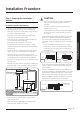
Installation Procedure Step 1 Choosing the installation location CAUTION • You have just purchased a system air conditioner and it has been installed by your installation specialist. • This device must be installed according to the national electrical rules. • If your outdoor unit exceeds a net weight of 60 kg, do not install it on a suspended wall, but stand it on a floor. Installation location requirements • Do not place the outdoor unit on its side or upside down.
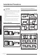
Installation Procedure Minimum clearances for the outdoor unit Install the unit in a place where water can drain smoothly. • If you have any difficulty finding installation location as prescribed above, contact your manufacturer for details. • Be sure to clean the sea water and the dust on the heat exchanger of the outdoor unit and apply a corrosion inhibitor on it. (At least once in a year.
300 or more Moving the outdoor unit with wire rope 600 or more 500 or more 300 or more 600 or more 600 or more 300 or more 1 Before carrying the outdoor unit, fasten two wire ropes of 8 m or longer, as shown in the figure. 2 To prevent damages or scratches effectively, insert a piece of cloth between the outdoor unit and the ropes. 3 Move the outdoor unit.
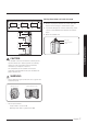
Installation Procedure Step 2 Fixing the outdoor unit in place Install the outdoor unit on a rigid and stable base to prevent disturbance from any noise caused by vibration. When installing the unit at a height or in a location exposed to strong winds, fix the unit securely to a support (i.e., a wall or a ground). Optional: Fixing the outdoor unit to a wall with a rack Designed to cut off residual vibration from outdoor unit to rack. (not supplied with product) Fix the outdoor unit with anchor bolts.
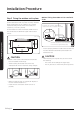
Step 3 Connecting the power cables, communication cable, and controllers You must connect the following three electrical cables to the outdoor unit: • • • Air conditioning system examples When using earth leakage circuit breaker (ELCB) for a single phase Main power cable The main power cable between the auxiliary circuit breaker and the outdoor unit. MCCB 1 The outdoor-to-indoor power cable between the outdoor unit and the indoor unit.
Installation Procedure Connecting the main power cable When using ELB for 1 phase and 3 phase 1-phase Electrical component box Power supply F1 1(L) 2(N) L F2 N MCCB ELB Installation Procedure Cable tie Outdoor-toindoor power cable Main power cable Communication cable 3-phase F1 1(L) 2(N) L1(R) L2(S) L3(T) F2 N The appearance of the unit may be different from the picture depending on the model.
Main power terminal block specifications • 1-phase terminal block specifications • AC090/100/120/140MXADKH, AC120MXASEH 1(L) 2(N) L AC090/100/120/140MXADNH F1 N 3-phase terminal block specifications F2 1(L) 2(N) L1(R) L2(S) L3(T) F1 N 10.1 15 12 F2 11.4 11.4 9.95 11.55 10.1 Main power cable specifications Single phase Model Indoor unit Outdoor unit Outdoor unit Hz Input current (A) Voltage range (V) Rated Min. Outdoor unit Max.
Installation Procedure 3-phase Model Outdoor unit Indoor unit Outdoor unit AC090MNMDKH AC090MXADNH Hz Input current (A) Voltage range (V) Rated Min. Outdoor unit Max. Cooling Heating Indoor unit Power supply Total MCA (A) MFA (A) 2.5 18.6 18.6 18.6 AC100MN4DKH 1.0 17.1 17.1 17.1 AC100NN4DKH 1.0 17.1 17.1 17.1 AC100MN4PKH 1.5 17.6 17.6 17.6 2.5 18.6 18.6 18.6 AC100MNCDKH 2.0 18.1 18.1 18.1 AC100MNTDEH 1.1 17.2 17.2 17.2 AC120MN4DKH 1.0 17.1 17.1 17.1 1.
Silence mode controller wiring diagram (AC090/100/120/140MXA**H) 3-phase L Outdoor unit N F1 F2 Indoor Unit Outdoor Unit F1 1(L) 2(N) L1(R) L2(S) L3(T) F2 N ASSY Control out 3-phase 4-wire main power cable (AC 380V) Communication cable Non-voltage contact NOTE Connecting the outdoor-to-indoor power cable and the communication cable • Lay the electrical wiring so that the front cover does not rise up when doing wiring work and attach the front cover securely.
Installation Procedure B D d1 E F L d2 t Nominal Nominal dimensions dimensions for cable for screw Standard Allowance Standard Allowance Standard Allowance Min. Min. Max. Standard Allowance Min. dimension dimension dimension dimension (mm²) (mm) (mm) (mm) (mm) (mm) (mm) (mm) (mm) (mm) (mm) (mm) (mm) (mm) 4 9.5 8 15 10 8 15 ±0.2 16 8 16 4/6 Installation Procedure 35 8 12 8 16.5 8 16 20 4.3 +0.2 0 9 28.5 8.4 +0.4 0 7.9 9 30 8.4 +0.4 0 1.15 ±0.2 9.5 13 33 8.4 +0.4 0 1.
Outdoor-to-indoor power and communication cables specifications Indoor power supply Power supply Max/Min (V) Indoor power cable 1ø, 220-240V, 50 Hz ±10% 1.5 mm² Ĺ, 3 wires Step 4 Optional: Extending the power cable 1 Prepare the following tools. Tools Spec Shape Crimping pliers MH-14 Connection sleeve (mm) 20xØ6.5 (HxOD) Insulation tape Width 19 mm Contraction tube (mm) 70xØ8.0 (LxOD) Communication cable 0.75 to 1.
Installation Procedure 3 Insert both sides of core wire of the power cable into the connection sleeve. • Method 1: Push the core wire into the sleeve from both sides. • Method 2: Twist the wire cores together and push it into the sleeve. Method 1 Method 2 Connection sleeve 6 Apply heat to the contraction tube to contract it. Contraction tube 7 After tube contraction work is completed, wrap it with the insulation tape to finish.
Step 5 Connecting the refrigerant pipe Maximum allowable length Items Single installation AC090MXAD*H AC100MXAD*H AC120MXAD*H AC120MXAS*H Applicable outdoor unit models AC140MXAD*H AC100MXAD*H AC120MXAD*H AC140MXAD*H Total pipe length (L1+…+Ln+1+a+b) - - 50 m 75 m Main pipe (L1) 50 m 75 m 30 m 50 m Max. distance among indoor units (D) - - 10 m 10 m Max. length after branch - - 15 m 15 m Max. height difference between outdoor and indoor units (h1) 30 m 30 m 30 m 30 m Max.
Installation Procedure 3 To prevent any gas from leaking out, remove all burrs at the cut edge of the pipe, using a reamer. Be sure to use C1220T-1/2H (Semi-hard) pipe for more than Ø19.05 mm. If you use C1220T-O (Soft) pipe for Ø19.05 mm, the pipe may be broken, which can result in an injury. 4 Slide a flare nut on to the pipe and modify the flare. D A 90° ±2° • Make at least one round: It will reduce noise and vibration 45° ± 2° CAUTION R 0.4 to 0.
Step 7 Installing oil traps Check the following list and install an oil trap. • Based on cooling operation, install it on the gas side pipe only. • Install the oil trap only in between the outdoor unit and the first branch joint and it should be installed at every 10 m. • Radius of curvature (R) on the oil trap are as follows; Pipe diameter (D, mm) 12.70 15.88 19.05 22.23 25.40 28.60 31.
Installation Procedure 3 Connect the charging hose of low pressure side of manifold gauge to the packed valve having a service port as shown at the figure. CAUTION • Connect the indoor and outdoor units using pipes with flared connections (not supplied). For the lines, use insulated, unwelded, degreased and deoxidized copper pipe, (Cu DHP type to ISO 1337 or UNI EN 12735-1), suitable for operating pressures of at least 4200 kPa and for a burst pressure of at least 20700 kPa.
Important information: regulation regarding the refrigerant used Indoor Unit This product contains fluorinated greenhouse gases. Do not vent gases into the atmosphere. Outdoor Unit 2 1 CAUTION • • Inform user if the system contains 5 tCO2e or more of fluorinated greenhouse gases. In this case, it must be checked for leakage at least once every 12 months, according to regulation No. 517/2014. This activity must be covered by qualified personnel only.
Installation Procedure Connecting communication line and wired remote controller Installing DPM • In case of 2 indoor units connection DPM allowable Outdoor and indoor unit models F1/F2 DPM allowable Outdoor and indoor unit models 2 IDUs connection 3 IDUs connection 4 IDUs connection Indoor Unit Indoor Unit Indoor Unit AC100MXAD*H AC052MN*DKH AC035MN*DKH - AC120MXAD*H AC060MN*DKH AC052MN*DKH AC035MN*DKH AC140MXAD*H AC071MN**KH AC052MN*DKH AC035MN*DKH Outdoor unit • Installation Proc
Instruction for installation and operation • • You should install the DPM according to the above installation specification and eliminate the factors that give electrical load to the both indoor units when installing and operating. (Heater / window / front door / ventilation / partition that divides space) You should provide sufficient instructions about the operation method and specification features to users and fill in caution phrases on wired remote controller when necessary.
Installation Procedure Step 11 Connecting the drain hose to the outdoor unit Step 12 Insulating the refrigerant pipes When using the air conditioner in the heating mode, ice may accumulate . During de-icing (defrost operation), the condensed water must be drained off safely. Consequently, you must install a drain hose on the outdoor unit, following the instructions below. Once you have checked that there are no leaks in the system, you can insulate the piping and hose.
Step 13 Checking the earthing Insulation Type (Heating/Cooling) Pipe size (mm) Pipe Standard [Less than 30°C, 85%] High humidity Remarks [over 30°C, 85%] EPDM, NBR Ø6.35~Ø9.52 Liquid pipe Gas pipe • 9t 9t Ø12.7~Ø19.05 13 t 13 t Ø6.35 13 t 19 t Ø9.52~Ø19.05 19 t 25 t Internal temperature is higher than 120°C If the power distribution circuit does not have a earthing or the earthing does not comply with specifications, an earthing electrode must be installed.
Installation Procedure 5 Carefully check the installation by measuring the earthing resistance with a earth resistance tester. If the resistance is above the required level, drive the electrode deeper into the ground or increase the number of earthing electrodes. ࢜ Defrost test mode Condition 1: The outdoor temperature is below 10°C. Condition 2: All the temperature conditions should meet the defrost conditions. 6 Connect the earthing wire to the electrical component box inside of the outdoor unit.
6 View mode: When the K4 switch is pressed, you can see information about our system state as below.
Installation Procedure 7 DIP switch option 8 Setting the address manually (high level controller) • ON ON Turn off the air conditioner, press and hold the K2 switch for a while to enter the Option mode. (Initial value: 00AU) – You cannot enter the Option mode when the air conditioner is running.
Extra Procedures Pumping down refrigerant Relocating the indoor and outdoor units WARNING • After installing the product, be sure to perform leak tests on the piping connections. After pumping down refrigerant to inspect or relocate the outdoor unit, be sure to stop the compressor and then remove the connected pipes. – Do not operate the compressor while a valve is open due to refrigerant leakage from a pipe or an unconnected or incorrectly connected pipe.
Extra Procedures Using the stop valve NOTE • Do not apply excessive force to the stop valve and always use special instruments. Otherwise, the stopping box can be damaged and the back sheet can leaks. • If the watertight sheet leaks, turn the axis back by half, tighten the stopping box, then check the leakage again. If there is no leakage any more, tighten the axis entirely. Opening the stop valve 1 Open the cap and turn the stop valve anticlockwise by using a hexagonal wrench.
Appendix Troubleshooting The table below list the self-diagnostic routines. For some of error codes, you must contact an authorized service centre. If an error occurs during the operation, it is displayed on the outdoor unit PCB LED, both MAIN PCB and INVERTER PCB. No.
Appendix No. Error Code Meaning Remarks 22 E441 Cooling operation restricted at outdoor temperature below Tcool_low value (default:0°C) 1. Check the range of temperature limited for cooling operation 2. Check the outdoor temperature sensor 23 E458 Fan speed error FAN1 ERROR 24 E461 Error due to operation failure of inverter compressor - 25 E462 System stop due to full current control - 26 E463 Over current trip / PFC over current error Check OLP sensor 27 E464 IPM Over Current(O.
COMMISSION DELEGATED REGULATION (EU) No 626/2011i) PRODUCT FICHE (ENERGY LABELLING OF AIR CONDITIONERS)ii) A Supplier's name - Samsung Electronics Co.. Ltd.
Appendix COMMISSION DELEGATED REGULATION (EU) No 626/2011i) PRODUCT FICHE (ENERGY LABELLING OF AIR CONDITIONERS)ii) A Supplier's name - Samsung Electronics Co.. Ltd.
COMMISSION DELEGATED REGULATION (EU) No 626/2011i) PRODUCT FICHE (ENERGY LABELLING OF AIR CONDITIONERS)ii) A Supplier's name - Samsung Electronics Co.. Ltd.
Appendix Appendix [ESPAÑOL-ES] [FRANÇAIS-FR] [ITALIANO-IT] [PORTUGUÊS-PT] A Nombre del proveedor Nom du fournisseur Nome del Fornitore Nome do fornecedor B Nombre del modelo (unidad interior/exterior) Nom du modèle (intérieur/extérieur) Nome del Modello (Unità Interna/Unità Esterna) Nome do modelo (interior/exterior) C Nivel de potencia acústica (interior/exterior) Niveau de puissance acoustique (intérieur/extérieur) Livello della potenza sonora (interno/esterno) Nível de potência sonora
>(ȁȁ+1,.
Appendix [MAGYAR-HU] Appendix iv [ČEŠTINA-CS] [SLOVENČINA-SK] Názov dodávateľa [ROMÂNĂ-RO] Forgalmazó neve Název dodavatele B Modellnév (Beltéri/kültéri) Názov modelu Název modelu (vnitřní/venkovní) (vnútorné/vonkajšie) Numele modelului (interior/exterior) C Zajszint (Beltéri/kültéri) Hladina akustického výkonu (vnitřní/venkovní) Hladina akustického výkonu (vnútorná/vonkajšia) Nivel de putere acustică (interior/exterior) D Hűtőközeg neve1) Název chladiva1) Chladivo1) Numele agentului fri
>ȻɔɅȽȺɊɋɄɂ %*@ [HRVATSKI-HR] [SLOVENČINA-SL] [DANSK-DA] A ɂɦɟ ɧɚ ɞɨɫɬɚɜɱɢɤ Naziv dobavljača Názov dodávateľa Leverandørens navn B ɂɦɟ ɧɚ ɦɨɞɟɥ ɜɴɬɪɟɲɧɨ ɜɴɧɲɧɨ ɬɹɥɨ Naziv modela (unutarnji/spoljni) Názov modelu (vnútorné/vonkajšie) Modelnavn (indendørs/udendørs) C ɇɢɜɨ ɧɚ ɚɤɭɫɬɢɱɧɚ ɦɨɳɧɨɫɬ ɜɴɬɪɟɲɧɨ ɜɴɧɲɧɨ ɬɹɥɨ Razina zvučne snage (u zatvorenom/otvorenom) Hladina akustického výkonu (vnútorná/vonkajšia) Lydeffektniveau (indenfor/udenfor) D ɂɦɟ ɧɚ ɯɥɚɞɢɥɟɧ ɚɝɟɧɬ Naziv rashladnog sredstva
Appendix [SVENSKA-SV] [SUOMI-FI] [EESTI-ET] [LATVIEŠU-LV] A Leverantörens namn Tavarantoimittajan nimi Tarnija nimi Piegādātāja nosaukums B Modellnamn (inomhus/utomhus) Mallin nimi (sisä/ulko) Mudeli nimi (sisetingimused/välistingimused) Modeļa nosaukums (iekštelpu/ārtelpu) C Ljudnivå (inomhus/utomhus) Äänitehotaso (sisä/ulko) Helivõimsuse tase (sisetingimused/välistingimused) Skaņas intensitātes līmenis (iekštelpu/ārtelpu) D Köldmedium1) Kylmäaineen nimi1) Jahutusaine nimi1) Aukstuma
[LIETUVIŲ KALBA-LT] [SRPSKI-SR] A Tiekėjo pavadinimas 1D]LY GREDYOMDþD B Modelio pavadinimas (naudojamo patalpose / lauke) 1D]LY PRGHOD XQXWUãQMD MHGLQLFD VSROMDãQMD MHGLQLFD C Garso galios lygis (patalpose / lauke) 1LYR EXNH XQXWUDãQMD VSROMQD MHGLQLFD D Šaldalo pavadinimas1) 1D]LY UDVKODGQRJ VUHGVWYD E GWP GWP F SEER SEER G Energijos suvartojimo efektyvumo klasė (SEER) .
Appendix [ESPAÑOL-ES] 1 Las fugas de refrigerante contribuyen al cambio climático. Cuanto mayor sea el potencial de calentamiento global (GWP) de un refrigerante, más contribuirá a dicho calentamiento su vertido a la atmósfera. Este aparato contiene un líquido refrigerante con un GWP igual a [2088].
[DEUTSCH-DE] 1 Der Austritt von Kältemittel trägt zum Klimawandel bei. Kältemittel mit geringerem Treibhauspotenzial tragen im Fall eines Austretens weniger zur Erderwärmung bei als solche mit höherem Treibhauspotenzial. Dieses Gerät enthält Kältemittel mit einem Treibhauspotenzial von [2088]. Somit hätte ein Austreten von 1 kg dieses Kältemittels [2088] Mal größere Auswirkungen auf die Erderwärmung als 1 kg CO2, bezogen auf hundert Jahre.
Appendix [MAGYAR-HU] 1 A hűtőközeg-szivárgás fokozza az éghajlatváltozást. Az alacsonyabb globális felmelegedési potenciállal (GWP) rendelkező hűtőközegek kevésbé járulnak hozzá a globális felmelegedéshez, ha a légkörbe jutnak, mint a magasabb együtthatójú típusok. A berendezés [2088] értékű globális felmelegedési potenciállal (GWP) rendelkező, folyékony halmazállapotú hűtőközeget tartalmaz.
[ȻɔɅȽȺɊɋɄɂ %*@ 1 Ɍɟɱɨɜɟɬɟ ɧɚ ɯɥɚɞɢɥɟɧ ɚɝɟɧɬ ɞɨɩɪɢɧɚɫɹɬ ɡɚ ɢɡɦɟɧɟɧɢɟɬɨ ɧɚ ɤɥɢɦɚɬɚ ɏɥɚɞɢɥɟɧ ɚɝɟɧɬ ɫ ɩɨ ɧɢɫɴɤ ɩɨɬɟɧɰɢɚɥ ɡɚ ɝɥɨɛɚɥɧɨ ɡɚɬɨɩɥɹɧɟ *:3 ɛɢ ɞɨɩɪɢɧɟɫɴɥ ɩɨ ɦɚɥɤɨ ɡɚ ɝɥɨɛɚɥɧɨɬɨ ɡɚɬɨɩɥɹɧɟ ɨɬɤɨɥɤɨɬɨ ɯɥɚɞɢɥɟɧ ɚɝɟɧɬ ɫ ɩɨ ɜɢɫɨɤ *:3 ɜ ɫɥɭɱɚɣ ɧɚ ɢɡɬɢɱɚɧɟ ɜ ɚɬɦɨɫɮɟɪɚɬɚ Ɍɨɡɢ ɭɪɟɞ ɫɴɞɴɪɠɚ ɬɟɱɟɧ ɯɥɚɞɢɥɟɧ ɚɝɟɧɬ ɫ *:3 ɪɚɜɟɧ ɧɚ > @ Ɍɨɜɚ ɨɡɧɚɱɚɜɚ ɱɟ ɚɤɨ NJ ɨɬ ɬɨɡɢ ɬɟɱɟɧ ɯɥɚɞɢɥɟɧ ɚɝɟɧɬ ɢɡɬɟɱɟ ɜ ɚɬɦɨɫɮɟɪɚɬɚ ɜɴɡɞɟɣɫɬɜɢɟɬɨ ɜɴɪɯɭ ɝɥɨɛɚɥɧɨɬɨ ɡɚɬɨɩɥɹɧɟ ɛɢ ɛɢɥɨ > @ ɩɴɬɢ ɩɨ ɜɢɫɨɤɨ ɨɬ NJ &22 ɡɚ ɩɟɪɢɨɞ ɨɬ
Appendix [SVENSKA-SV] 1 Läckande köldmedium bidrar till klimatförändringen. Köldmedier med lägre global uppvärmningspotential (GWP) bidrar mindre till den globala uppvärmningen än köldmedier med högre GWP-värde, om de skulle läcka ut i atmosfären. Den här enheten innehåller ett köldmedium med ett GWP-värde som är lika med [2088].
[LATVIEŠU-LV] 1 Aukstumaģenta noplūde veicina klimata pārmaiņas. Aukstumaģents ar zemāku globālās sasilšanas potenciālu (GWP) globālo sasilšanu veicina mazākā mērā nekā aukstumaģents ar augstāku GWP, ja notiek noplūde atmosfērā. Šajā iekārtā izmantots aukstumaģenta šķidrums, kura GWP atbilst [2088]. Tas nozīmē, ka gadījumā, ja atmosfērā noplūstu 1 kg šī aukstumaģenta šķidruma, ietekme uz globālo sasilšanu 100 gadu laika posmā būtu [2088] reizes lielāka, salīdzinot ar 1 kg CO2.
Memo 50 English
English 51
SAMSUNG ELECTR ONICS CO., LTD . 107, Hanamsandan 6beon-ro, Gwangsan-gu, Gwangju-si, Korea 62218 Samsung Electronics Service Department PO Box 12987, Blackrock, Co. Dublin. Ireland or Blackbushe Business Park, Yateley, GU46 6GG.