ECO HEATING SYSTEM OUTDOOR UNIT Model : AEX160EDEHA AEX140EDEHA AEX125EDEHA AEX160EDGHA AEX140EDGHA AEX125EDGHA AEX100EDEHA AEX060EDEHA ECO HEATING SYSTEM HYDRO UNIT AEN160YDEHA AEN160YDGHA AEN080YDEHA CONTENTS 1. Precautions 2. Product Specifications 3. Disassembly and Reassembly 4. Troubleshooting 5. PCB Diagram 6. Wiring Diagram 7. Schematic Diagram 8. Reference Sheet Refer to the service manual in the GSPN(see the rear cover) for the more information. RC160MHXGA_SM_E_34513A(1)_co.
Contents 1. Precautions ..............................................................................................................................................3 1-1 Precautions for the Service ..........................................................................................................................................3 1-2 Precautions related to static electricity and PL...................................................................................................
Contents 4-5 Troubleshooting by symptoms .............................................................................................................................53 4-5-1 Communication error after finishing tracking (E202) ........................................................... 53 4-5-2 Time out (1min.) of communication error between MAIN PBA and INV. PBA (E203) ............ 54 4-5-3 Temperature sensor error (E221, E231, E251, E320 ) ...................................................................
1. Precautions 1-1 Precautions for the Service O Use the standard parts when replacing the electric parts. – Confirm the model name, rated voltage, rated current of the electric parts. O When repairing the equipment, connection of the harness parts must be firm and solid. – A loose connection may cause noise or other malfunction. O When assembling and disassembling the equipment while it is laid down, lay it on soft cloth. – Otherwise it may scratch the back of the exterior of the product.
Precautions 1-3 Precautions for the Safety O Do not pull any electric wires and do not touch an auxiliary power switch with a wet hand. – There is a danger of electric shock or fire. O In case any wire or power plug has been damaged, replace it to eliminate any possible danger. O Do not bend the power cord by force and do not put any heavy object on the power cord. – There is a danger of electric shock or fire. O Do not use multi socket. – There is a danger of electric shock or fire.
Precautions 1-4 Precautions for handling a system containing refrigerants All system containing refrigerants shall be removed under regional regulations prior to the disposal to prevent the potential health and environmental consequences. O Harmful for human body – When emitted liquid refrigerant contacts human body, contacted area may get frostbite, blister or become numb. If refrigerant leaks in airtight area, lack of oxygen may cause suffocation.
2. General Overview 2-1 Features of the System POWER SAVING EHS(Eco Heating System) considers the trend in air conditioner use. It optimizes the energy efficiency of loads ranging from partial to full. It achieves an excellent energy effect for the users of the air conditioner. Samsung patented compressor Samsung has been researching and developing compressors since the 70's. It has developed power saving compressors for more than thirty years.
General Overview Quiet night EHS(Eco Heating System)'s outdoor machine can be set to quiet nighttime operation mode. The outdoor machine executes quiet operation (sleeping mode) after six hours. After 12 hours, it returns to the previous mode automatically.
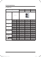
2-2 Product Specifications 2-2-1 Outdoor Unit AEX160EDGHA AEX140EDGHA AEX125EDGHA 3phase 16kW 3phase 14kW 3phase 12.
General Overview Product Specifications (cont.) Item Image POWER CONSUMPTION (110%↓) Running Current (110%↓) AEX125EDEHA AEX100EDEHA AEX060EDEHA 1phase 14kW 1phase 12.5kW 1phase 10kW 1phase 5.
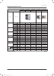
General Overview NO DIVISION UNIT AEN160YDGHA AEN160YDEHA AEN080YDEHA 1 POWER SOURCE V/㎐ 3P, 380-415~, 50Hz 1P, 220-240V~, 50Hz 1P, 220-240V~, 50Hz 2 "POWER CONSUMPTION (Pump 3 Step, 110%↓)" W 151 151 132 3 "Running Current (Pump 3 Step, 110%↓)" A 0.234 0.691 0.604 4 "MAX Current (Pump 3 Step+Backup Heater 2 Step)" A 9.55 28.2 18.
2-3 Specifications of optional items 2-3-1 Accessories Item Samsung Electronics RC160MHXGA_SM_E_34513A(1)_1~3.indd 11 Description Code No.
3. Disassembly and Reassembly Q Hand Tool sets Item Remark +Screw Driver Adjustable wrench –Screw Driver Nipper Electric Motion Driver L-Wrench Torque Lench Latchet Lench 12 RC160MHXGA_SM_E_34513A(1)_1~3.
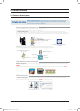
3-1 Hydro Unit Q AEN160YD䭑/AEN080YD䭑 Be sure that the power switch is in the “OFF” and the power source cord shall be unplugged prior to disassembly and reassembly works. No Parts 1 Panel 2 Controller & Manometer Procedure Remark 1) Remove 4 cover screws from the Hydro Unit. (Use + Screw Driver) 1) Remove 3 screws from it. (Use + Screw Driver) 2) Remove pressure sensor by adjustable wrench. (Use adjustable wrench-230kgf·cm) 3) Pull the manometer out. 4) Pull the LED display up and out.
Disassembly and Reassembly No Parts Procedure Remark 5) Remove the connector from the PCB board. 6) Remove the upper case of the controller. 7) Remove 5 screws. Set a side the drain pan and hydro unit. 14 RC160MHXGA_SM_E_34513A(1)_1~3.
Disassembly and Reassembly No Parts 3 Water Pump Procedure Remark 1) Remove 4 screws. (Use + Screw Driver) 2) Remove the cabi-control top. 3) Remove the flow switch and connector. 4) Remove a pipe from the backup Heater. (Use adjustable wrench-380kgf·cm) Use the Torque Wrench when you assemble it. Samsung Electronics RC160MHXGA_SM_E_34513A(1)_1~3.
Disassembly and Reassembly No Parts Procedure Remark 5) After removing insulation material, remove the Thermostat. 6) Remove 2 screws. (Use + Screw Driver) 7) Remove 2 screws. (Use + Screw Driver) 8) Pull the water pump & pipes up, out. 16 RC160MHXGA_SM_E_34513A(1)_1~3.
Disassembly and Reassembly No Parts Procedure 4 Expansion Vessle 1) Remove the tube of the expansion vessel and the backup heater by adjustable wrench. (Use adjustable wrench-150kgf·cm) Remark Use the Torque Wrench when you assemble it. 2) Remove 2 screws. (Use + Screw Driver) 3) After removing the nut. Pull the bracket out. 4) Pull the expansion vessel up, out. 5 Plate Heat Exchanger Samsung Electronics RC160MHXGA_SM_E_34513A(1)_1~3.indd 17 1) Remove 4 insulations.
Disassembly and Reassembly No Parts Procedure Remark 2) Remove 4 Thermostats. 3) Remove the Thermostat conector on the PCB of the Control box. 4) Remove the pipe from the Backup Heater. (Use adjustable wrench-380kgf·cm) Use the Torque Wrench when you assemble it. 5) Remove 6 screws. (Use + Screw Driver) 6) Pull the PHE out of the unit. 18 RC160MHXGA_SM_E_34513A(1)_1~3.
Disassembly and Reassembly No Parts Procedure 6 Control Box 1) Remove 4 Thermostats. Set a side the terminal block and PBA case. (Use + Screw Driver) Remark 2) Remove Conectors. 3) Remove 3 screws. (Use + Screw Driver) 4) Pull the cabi-control bottom out by pushing as indicated diretion.
Disassembly and Reassembly No Parts 7 Backup Heater Procedure Remark 1) Remove the Drain Hose. 2) After removing 4 screws, set a side the backup heater and the unit. (Use + Screw Driver) 20 RC160MHXGA_SM_E_34513A(1)_1~3.
3-2 Outdoor Unit Q AEX100ED✳/AEX125ED✳/AEX140ED✳/AEX160ED✳ No Parts 1 CABI FRONT RH Procedure Remark You must turn off the power before disassembling. 1) Unscrew and remove the three screws on the CABI FRONT RH. (Use '+' type screw driver) 2 CABI TOP 3 CABI INSTALL FRONT Samsung Electronics RC160MHXGA_SM_E_34513A(1)_1~3.indd 21 1) Unscrew and remove the nine screws on each side of the CABI TOP. (Use '+' type screw driver) 1) Unscrew and remove the screw on the CABI INSTALL FRONT.
Disassembly and Reassembly No Parts 4 GUARD COND Procedure Remark 1) Pull the sensor from Guard Cond. 2) Unscrew and remove the four screws on the GUARD COND. (Use '+' type screw driver) 22 RC160MHXGA_SM_E_34513A(1)_1~3.
Disassembly and Reassembly No Parts 5 CABI BACK RH Procedure Remark 1) Pull the sensor from the CABI BACK RH. 2) Unscrew and remove the nine screws on each side the CABI BACK RH. (Use '+' type screw driver) Samsung Electronics RC160MHXGA_SM_E_34513A(1)_1~3.
Disassembly and Reassembly No 6 Parts Procedure Remark CABI INSTALL BACK 1) Unscrew and remove the 8 screws on the CABI FRONT LF. (Use '+' type screw driver) 24 RC160MHXGA_SM_E_34513A(1)_1~3.
Disassembly and Reassembly No Parts Samsung Electronics RC160MHXGA_SM_E_34513A(1)_1~3.
Disassembly and Reassembly No Parts 7 FAN 26 RC160MHXGA_SM_E_34513A(1)_1~3.indd 26 Procedure Remark 1) Turn the two nuts as shown in the picture and remove them.
Disassembly and Reassembly No Parts Procedure 8 MOTOR 1) Remove the fan. 2) Unscrew and remove the eight motor screws. (Use '+' type screw driver) Remark 3) Disconnect the motor wire from the Ass'y Control Out. Samsung Electronics RC160MHXGA_SM_E_34513A(1)_1~3.
Disassembly and Reassembly No Parts 9 BRACKET MOTOR 28 RC160MHXGA_SM_E_34513A(1)_1~3.indd 28 Procedure Remark 1) Unscrew and remove the two screws on the BRACKET MOTOR.
Disassembly and Reassembly No Parts 10 CONTROL OUT Procedure Remark 1) Disconnect the six connectors form the ASSY CONROL OUT 2) Unscrew and remove the three screws on the CONTROL OUT. (Use '+' type screw driver) 3) Separate the ASSY CONTROL OUT.
Disassembly and Reassembly No Parts 11 ASSY 4WAY VALVE Procedure Remark 1) Purge the coolant first. 2) Unscrew and remove the four screws on the SERVICE VALVE. (Use '+' type screw driver) 3) Separate the pipe from the Entrance/Exit using a welder. When removing the compressor, heat exchanger and pipe, purge the completely and remove the pipe with a welding flame. 30 RC160MHXGA_SM_E_34513A(1)_1~3.
Disassembly and Reassembly No Parts 12 COMPRESSOR Procedure Remark 1) Unscrew and remove the nut on the COVER TERMINAL. (Use adjustable wrench) 2) Separate the compressor wire. 3) Separate the COMPRESSOR FELT SOUND. 4) As shown in the picture, unscrew and bottom. (Use Adjustable Wrench) Samsung Electronics RC160MHXGA_SM_E_34513A(1)_1~3.
Disassembly and Reassembly No Parts 13 ASSY COND OUT 32 RC160MHXGA_SM_E_34513A(1)_1~3.indd 32 Procedure Remark 1) Unscrew remove the two screws on each side of the ASSY COND OUT.
Disassembly and Reassembly Q AEX060EDEHA No Parts Procedure 1 Common Work 1) Loosen 1 fixing screw of the Cover-Control and detach the Cover Control. Remark 2) Loosen fixing screws and detach the Cabinet-Upper. 3) Loosen 1 screw fixed to assemble Control Box with Cabinet-Side RH. 4) Loosen 6 fixing screws and detach the Cabinet-Side RH. Samsung Electronics RC160MHXGA_SM_E_34513A(1)_1~3.
Disassembly and Reassembly No Parts Procedure Remark 5) Loosen 2 screws fixed on the Guide Condenser. 6) Loosen fixing screws of the Cabinet Front. 34 RC160MHXGA_SM_E_34513A(1)_1~3.
Disassembly and Reassembly No Parts 2 Fan & Motor Procedure Remark 1) Detach the Nut Flange like the picture on the right side. (Turn clockwise because the screw is left-handed.) 2) Detach the Fan Propeller. 3) Loosen 4 fixing screws to detach the Motor. 4) Disconnect the wire between Ass’y Control Out and Motor. 5) Loosen 2 fixing screws and detach the Bracket Motor. 3 Ass’y Control Out Samsung Electronics RC160MHXGA_SM_E_34513A(1)_1~3.
Disassembly and Reassembly No Parts 4 Heat Exchanger Procedure Remark 1) Release the refrigerant at first. 2) Loosen fixing screw. 3) Disassemble the pipes in both inlet and outlet with welding torch. 4) Detach the Heat Exchanger. Before you disassemble the pipes and Condenser, be sure that there should be no refrigerant remained in the unit. 1) Loosen fixing screw(CCW) and detach the Heat Exchanger 5 Compressor 1) Loosen the fixing nut and detach the Compressor Lead Wire.
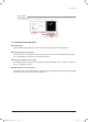
4. Troubleshooting 4-1 Wired remote controller - If an error occurs, ( ) icon will be displayed on the wired remote controller. - Press the Test button to see the error code. Error mode Contents Measure Product operation in error condition Outdoor unit/ Compressor/Indoor unit Error type Indoor unit communication error Check the communication cable of indoor unit.
Wired remote controller (cont.
Wired remote controller (cont.
4-2 Troubleshooting by symptoms 4-2-1 Communication error after finishing Tracking Indoor unit display Communication error between the indoor and outdoor unit for two minutes Symptom Communication error between the indoor unit and outdoor unit Failure No Is there a response from the indoor PCB? (LED900 (RED) is not ON) Check the communication cable and replace the indoor unit PCB LED01 Yes Remove the communication cable connecting the outdoor unit to indoor unit, and measure the signal on LINE 2 o
Troubleshooting 4-2-2 EEPROM circuit failure Indoor unit display EEPROM circuit failure Symptom EEPROM component failure, EEPROM circuit parts missing/damaged/soldering failure Failure Are the EEPROM circuit components in good conditions? (missing components / damage / soldering failure) Yes Replace the PCB if the restart fails No Restart the unit after replacing the PCB Samsung Electronics RC160MHXGA_SM_E_34513A(1)_4.
4-3 Hydro Unit 4-3-1 EEPROM error Outdoor unit display Indoor unit display ×(Operation) ◑(Timer) ◑(Fan) ◑(Filter) ×(Defrost) t Communication failure between EEPROM and MICOM Criteria Cause of problem t 1$# SFQMBDFNFOU EVF UP EFGFDUJWF &&130. 1.
Troubleshooting : Error due to abnormal data of Wired remote controller thermistor value 4-3-2 x x x(x x x : The address of the error occurred indoor unit) Outdoor unit display Wired remocon display t Refer to how to determine below Criteria Cause of problem t Wired remocon room thermistor has a defective OPEN/SHORT 1. How to check Does wired remocon room thermistor connector come out of the PBA? Yes Re-start after put the connetor in the PBA. No Ex) In case of 26°C – its resistance : around 10.
Troubleshooting : Error due to abnormal data of Water outlet thermistor value 4-3-3 x x x(x x x : The address of the error occurred indoor unit) Outdoor unit display Wired remocon display t Refer to how to determine below Criteria Cause of problem t Water outlet thermistor has a defective OPEN/SHORT 1. How to check Does Water outlet thermistor connector come out of the PBA? No Yes Re-start after put the connetor in the PBA. Ex) In case of 26°C – its resistance : around 10.
Troubleshooting : Error due to abnormal data of DHW tank thermistor value 4-3-4 Outdoor unit display x x x (x x x : The address of the error occurred indoor unit) Wired remocon display t Refer to how to determine below Criteria Cause of problem t DHW tank thermistor has a defective OPEN/SHORT 1. How to check Does water tank thermistor connector come out of the PBA? Yes Re-start after put the connetor in the PBA.
Troubleshooting 4-3-5 Water pump & flow switch OFF Wired remocon display t Refer to how to determine below Criteria Cause of problem t Flow switch signal is off during 10seconds when the water pump signal is ON 1. How to check Does flow S/W connector come out of the PBA? Yes Re-start after put the connetor in the PBA. No After putting out the connector(F/S) from the PBA Measure its status is OPEN or SHORT? Yes Is it OPEN? No Flow S/W needs to be replaced.
Troubleshooting 4-3-6 Water pump & flow switch ON Wired remocon display t Refer to how to determine below Criteria Cause of problem t Flow switch signal is on during 10seconds when the water pump signal is off) 1. How to check Does flow S/W connector come out of the PBA? Yes Re-start after put the connetor in the PBA.
Troubleshooting 4-3-7 Hydro unit temperature sensor(open/short) Error Mode E901, E902, E903, E904, E906 Symptom In case of open or short circuit of indoor temperature sensor Short or leakage of the corresponding sensor Failure Is temperature sensor disconnected from the connector in PCB? No Yes Restart the system after connecting to the PCB connector Remove the temperature sensor connector from the PCB and measure the resistance between two terminals
Troubleshooting 4-3-8 Communication error after finishing Tracking(Hydro unit) Error Mode E201, E202 Symptom Communication error between the Control KIT and outdoor unit for two minutes Communication error between the Control KIT unit and outdoor unit Failure Is there a response from the Control KIT PCB? (LED01 (RED) is not ON) No Check the communication cable and replace the Control KIT unit PCB Yes LED900 Remove the communication cable connecting the outdoor unit to Control KIT unit, and measur
4-4 Items to check before diagnostics 4-4-1 Test run mode and view mode 䯴 Display Option Key KEY KEY operation 7-segment display Press once : Heating test run K1 Press twice : Defrost test run Press 3times : Finishing test mode - Press once : Cooling test run K2 Press twice : Finishing test mode K3 Reset K4 View mode 7-segment display Refer to View mode display KEY (K1~K4) ■ VIEW mode display Display Number of press Display contents Units Segment 1 0 Communication State 1 Order frequency
Troubleshooting 4-4-2 Troubleshooting for outdoor unit If an error occurs during the operation, it is displayed on the outdoor unit PCB LED, both MAIN PCB and INVERTER PCB. No. LED Display Red Green Yellow Displayed PCB Assy - z | MAIN/INVERTER 1 z | MAIN z z | 2 Meaning Remarks Error Code Normal operation (MAIN : Indoor¥Outdoor : Green ON) (INVERTER : MAIN PCB¥INVERTER PCB : Green ON) - Control Kit quantity is mismatched.
Troubleshooting Troubleshooting for outdoor unit(con.) If an error occurs during the operation, it is displayed on the outdoor unit PCB LED, both MAIN PCB and INVERTER PCB. LED Display Red Green Yellow Displayed PCB Assy 24 z | z MAIN/INVERTER Comp. wire missing error Check Comp.
4-5 Troubleshooting by symptoms 4-5-1 Communication error after finishing tracking (E202) 1. Check items 1) Is the communication cable short/open? 2) Is there a response from the Control kit PCB? 2. Check procedure Is there a response from the $POUSPM kit PCB? (LED901 (ORN) in NOT blinking) No Check the communication cable and exchange the $POUSPM kit PCB No Connect the power/communication cable correctly.
Troubleshooting 4-5-2 Time out (1min.) of communication error between MAIN PBA and INV. PBA (E203) 1. Check items 1) Is the communication cable connected properly between MAIN PBA and INVERTER PBA? 2) Is the power cable connected correctly? 2.
Troubleshooting 4-5-3 Temperature sensor error (E221, E231, E251, E320) 3LQ QR &1 LQ 0$,1 3%$ (UURU 7HPS VHQVRU FRGH 2XWGRRU ( &RQGHQVHU ( 'LVFKDUJH ( 2/3 ( 1. Check items 1) Is the sensor connected correctly (CN43 in MAIN PBA)? 2) Is the postion of sensor correct? 3) Does the value of resistance satisfy the each temperature condition? 2.
Troubleshooting 4-5-4 Fan error (E458, E475) FAN 1 error(E458), FAN 2 error(E475) 1. Check items 1) Are the input power voltage and power connection correct? 2) Is the motor wire connected to the outdoor PCB correctly? 3) Is there no obstacle at the surrounding of motor and propeller? 4) Does the driver in the motor case broken? 2.
Troubleshooting Fan error (E458, E475) (cont.) Cont. Yes Is the Pin voltage #6 - #3 of CN90 and 91 changed high(4-5V) and low(0-1V) in case of making manual rotation slowly? Yes Exchange INVERTER PCB No Is the Pin voltage #7 - #3 of CN90 and 91 low(0-1V) in normal rotation? No Exchange the FAN motor Yes Exchange INVERTER PCB Samsung Electronics RC160MHXGA_SM_E_34513A(1)_4.
Troubleshooting 4-5-5 Compressor error (E461, E467) Compressor starting error(E461), Compressor wire missing error(E467) 1. Check items 1) Is the power connected properly? 2) Is the connector of compressor connected correctly? 3) Is the resistance normal between each phase for compressor ? 2.
Troubleshooting 4-5-6 Current trip error (E462, E463) Primary current trip error(E462), Over current trip / PFC over current error(E463) 1. Check items 1) Is the voltage of power suitable? 2) Is refrigerant charged? 3) Does the fan of outdoor unit work normally? 4) Is there any obstacle around indoor and outdoor unit? 2.
Troubleshooting 4-5-7 IPM(IGBT module) over current error (E464) 1. Check items 1) Is refrigerant charged? 2) Does the compressor work normally? 3) Is the connection of compressor correctly? 4) Is there any obstacle around indoor and outdoor unit? 2.
Troubleshooting cont. Is the value of resistance megaȍ between compressor and outdoor unit body? No Exchange the compressor Yes Are the position and measured value of temperature sensor normal? No reposition the sensor Yes Exchange INVERTER PCB Samsung Electronics RC160MHXGA_SM_E_34513A(1)_4.
Troubleshooting 4-5-8 DC-link voltage under/over error (E466) 1. Check items 1) Is the input power normal? 2) Is the AC power connected correctly? 2.
Troubleshooting 4-5-9 GAS leak error(E554) 1. Check items 1) Is refrigerant charged? 2) Is the evaporator sensor of indoor unit connected correctly? 2.
Troubleshooting 4-5-10 The other errors Error code Meaning Troubleshooting E177 Emergency stop Indoor unit ($POUSPM kit) orders emergency stop. Check the indoor unit ($POUSPM kit). E201 Control Kit quantity is mismatched. Control kit quantity must be matched with outdoor unit 1 by 1. Check the $POUSPM kit quantity. It must be 1EA. E403 Detection of outdoor freezing when compressor stops. Outdoor unit (Condenser) froze. Check condenser. E404 Protection of outdoor overload when compressor stops.
Troubleshooting 4-5-11 In case of heating at the cooling mode or cooling at the heating mode 1. Troubleshooting procedure Is the Thermo ? Yes Change the setting temperature of remote control. Yes Operate it with a heating mode as soon as the defrosting is shed. Yes After 3 minutes, cooling and heating start automatically.
Troubleshooting In case of heating at the cooling mode or cooling at the heating mode (cont.) From the previous page Does the EEV operate normally? No No Is much frost in the heat exchanger? Connect the connector. Yes Check the resistance value of EEV coil. NG EEV coil error OK Yes Is much frost in the heat exchanger? No Exchange the out PCB.
Troubleshooting 4-5-12 Outdoor unit is not powered on – Initial diagnosis 1. Check items 1) Is the power supply voltage 380V? 2) Is the AC power connected correctly? 3) Are the LEDs in the main PCB and inverter PCB of the outdoor unit ON? 4) Is the input power voltage of the indoor unit 220V? 5) Is the wired remote controller connected correctly? 2. Check procedure Turn o he main power switch (circuit break of power outlet) and turn on again after 30 seconds.
Troubleshooting 4-5-13 Outdoor unit power supply error 1. Checklist: 1) Are the input power voltage and power connection correct? 2) Is there any Fuse Short of the indoor or outdoor unit? 3) Is any LED lit on both MAIN PCB and INVERTER PCB? 4) Are Reactor wires of the outdoor unit connected correctly? 2.
5. PCB Diagram 5-1 Hydro unit This Document can not be used without Samsung’s authorization. 1 ① TB-A – POWER IN / HEATER #1(L) : Phase L 2 ② TB-B – TERMINAL BLOCK 3 ③ CN2 - DOWNLOAD 4 5 6 7 8 ④ S/G – SMART GRID #1 : SMART GRID sensor #2 : GND #1~26 : Check WIRING DIAGRAM #2(N) : Phase N #3 : HEATER #4 : HEATER ⑤ F/S – FLOW S/W #1 : FLOW SWITCH sensor #2 : GND Samsung Electronics RC160MHXGA_SM_E_34513A(1)_5~8.
5-2 Outdoor Unit 䯴 MAIN PCB This Document can not be used without Samsung’s authorization. 1 5 2 6 3 16 15 70 RC160MHXGA_SM_E_34513A(1)_5~8.
PCB Diagram ①G CN11-AC POWER ② CN74-AC LOAD1 ③ CN75-4WAY V/V ④ CN71-AC LOAD2(Option) #1-#3 : 220~240Vac #1-#3 : 220~240Vac #1-#3 : 220~240Vac #1-#3 : 220~240Vac ⑤G CN37-Micom Download #1 : RXD_INV #2 : TXD_INV #3, #8 : N.C #4 ~ #7 : Data signal #9 : GND #10 : DC 5V ⑥ CN35-AS-PRO #1 : DC 5V #2 : MODE #3 : Reset #4~#6 : GRID_3/1/2 #7 : GND ⑦G CN43-Sensor #1-#2 : Outdoor Temp. #3-#4 : Cond. Temp. #5-#6 : Discharge Temp. #7-#8 : OLP Temp.
PCB Diagram 䯴 INVERTER PCB This Document can not be used without Samsung’s authorization. 1 2 6 7 9 3 4 5 8 ① RST-AC POWER 3phase #R : AC 380~400V : WHT #S : AC 380~400V : BRN #T : AC 380~400V : BLK ② CN100-AC POWER #1-#3 : AC 220~240V ③ CN31-MAIN COMM #1 : RXD , #2 : TXD #3 : GND, #4 : DC 5V #5 : DC 12V, #6 : INV. SMPS signal ④ CN22-Downloader #1 : RXD_ATARO, #2 : TXD_ATARO #3, #8 : N.
PCB Diagram 䯴 EMI PCB This Document can not be used without Samsung’s authorization. 1 2 ① RST-AC POWER 3phase #R : AC 380~400V : WHT #S : AC 380~400V : BRN #T : AC 380~400V : BLK Samsung Electronics RC160MHXGA_SM_E_34513A(1)_5~8.
PCB Diagram 䯴 Heater PCB This Document can not be used without Samsung’s authorization. 1 ① AC POWER INPUT #1 AC POWER LINE - LIVE #2 AC POWER LINE - NEUTRAL 74 RC160MHXGA_SM_E_34513A(1)_5~8.
5-3 Parts List 䯴 MAIN PCB Location Code Description DB93-11109D ASSY PCB MAIN-OUT Spec. DB93-11363C ASSY PCB MANUAL EHS Remko 14KW,Inverter Platform #4, #5, #6 MAIN,Y,SMPS,TOP264VG,5Vdc, 12Vdc EHS Outdoor Main,14KW REMKO ADHESIVESILICON 0201-001982 ADHESIVE-SIL TSE3854DS-W,White,2.2,MIL-A-46146B,UL94V-0 SOLDER-BAR 0202-001338 SOLDER-BAR SOLDER-WIRE 0202-001608 SOLDER-WIRE FLUX LeeD-free Solder BAR,W20L350H8,99.3Sn/0.7Cu/0.01 P LFC7-107,D0.8,99.3Sn/0.7Cu/0.
PCB Diagram 䯴 MAIN PCB(cont.) Location Code COIL01 DB27-00082A ASSY CW EARTH DB93-05379G Description Spec. Q`ty Unit SA/ SNA COIL CHOKE CV305400SJ,RC100PHXEA,GLOBAL 4WAY,40mH,+50~30%,706mohm,0.5A,13*7*5,16*18.5*10,3.4mm*8.4m m,1.2mm,PAD,25℃~+105℃ 1 PC SNA DB93-11372C ASSY CONNECTOR WIRE EARTH ASSY PCB AUTO EHS Outdoor Main,14KW REMKO 1 PC SNA R110 2003-000855 R-METAL OXIDE(S) 47Kohm,5%,3W,AA,TP,6x16mm 1 PC SNA C103 2201-000322 C-CERAMIC,DISC 2.
PCB Diagram 䯴 MAIN PCB(cont.) Spec. Q`ty Unit SA/ SNA DIODE-TVS SMBJ5.0CA,6.4/-/7.
PCB Diagram 䯴 MAIN PCB(cont.) Location Code Description Spec.
PCB Diagram 䯴 MAIN PCB(cont.) Location Code Description Spec.
PCB Diagram 䯴 INVERTER PCB Location Code Description Spec. Q`ty Unit SA/ SNA - DB93-11114A ASSY PCB MAIN-INVERTER RC100DHXGA, RC100PHXGA, RC125PHXGA, RC125DHXGA,Inverter Platform #6,Y,SMPS,TOP243P,3.3V, 5V, 12V, 15V 1 PC SA - DB93-11362A ASSY PCB MANUAL RC100DHXGA, RC140DHXGA,Inverter #6, 3phase 1 PC SNA ADHESIVESILICON 0201-001982 ADHESIVE-SIL TSE3854DS-W,White,2.2,MIL-A-46146B,UL94V-0 0.02 KG SNA SOLDER BAR 0202-001338 SOLDER-BAR LeeD-free Solder BAR,W20L350H8,99.3Sn/0.
PCB Diagram 䯴 INVERTER PCB(cont.) Location Code Description Spec. Q`ty Unit SA/ SNA R101 2003-000855 R-METAL OXIDE(S) 47Kohm,5%,3W,AA,TP,6x16mm 1 PC SNA SNA R108 2006-001149 R-CEMENT,NON 1Kohm,5%,15W,CA,BK,48x12.5x12.5mm 1 PC C101 2201-000154 C-CERAMIC,DISC 10nF,+80-20%,2000V,Y5P,20x5mm,7.5mm 1 PC SNA C102 2201-000322 C-CERAMIC,DISC 2.2nF,10%,2000V,Y5P,13x5mm,10mm 1 PC SNA C103 2201-000551 C-CERAMIC,DISC 0.47nF,10%,1000V,Y5P,6.
PCB Diagram 䯴 INVERTER PCB(cont.) Location Code Description Spec.
PCB Diagram 䯴 INVERTER PCB(cont.) Location Code Description Spec.
PCB Diagram 䯴 INVERTER PCB(cont.) Location Code Description Spec. Q`ty Unit SA/ SNA R701 2007-000084 R-CHIP 4.7Kohm,5%,1/10W,TP,1608 1 PC SNA R702 2007-000084 R-CHIP 4.7Kohm,5%,1/10W,TP,1608 1 PC SNA R703 2007-000084 R-CHIP 4.7Kohm,5%,1/10W,TP,1608 1 PC SNA R905 2007-000084 R-CHIP 4.7Kohm,5%,1/10W,TP,1608 1 PC SNA R403 2007-000087 R-CHIP 6.8Kohm,5%,1/10W,TP,1608 1 PC SNA R410 2007-000087 R-CHIP 6.8Kohm,5%,1/10W,TP,1608 1 PC SNA R812 2007-000087 R-CHIP 6.
PCB Diagram 䯴 INVERTER PCB(cont.) Location Code Description Spec. Q`ty Unit SA/ SNA R107 2007-007342 R-CHIP 1.82Kohm,1%,1/10W,TP,1608 1 PC SNA R106 2007-007445 R-CHIP 9.
PCB Diagram 䯴 INVERTER PCB(cont.) Location Code Description Spec. Q`ty Unit SA/ SNA C324 2203-002002 C-CER,CHIP 0.
PCB Diagram 䯴 EMI PCB Code Description Spec. Q`ty Unit DB93-11111A ASSY PCB SUB-EMI GLOBAL-4WAY OUTDOOR,Inverter Platform #6 3Phase EMI,N 1 PC SA/ SNA SA 0201-001982 ADHESIVE-SIL TSE3854DS-W,White,2.2,MIL-A-46146B,UL94V-0 0.01 KG SNA Location ADHESIVESILICON VA01 1405-001204 VARISTOR 670Vdc,4500A,17x6.3mm,BK 1 PC SNA VA02 1405-001204 VARISTOR 670Vdc,4500A,17x6.3mm,BK 1 PC SNA VA03 1405-001204 VARISTOR 670Vdc,4500A,17x6.
PCB Diagram 䯴 HEATER PCB REF Part No. Spec CN02 3711-003406 HEADER-BOARD TO CABLE;1WALL,2P,1R,7.92MM,STRAIGHT, (YEL) HEADER-BOARD TO CABLE;1WALL,2P/3P,1R,7.92mm,STRAIG (WHT) CN03 3711-000203 FUSE-L 3602-001012 FUSE-BLOCK;500V,-,100MOhm FUSE-L 3601-000416 250V,1A,FAST-ACTING,GLASS,5.2x20mm FUSE-N 3602-001012 FUSE-BLOCK;500V,-,100MOhm FUSE-N 3601-000416 250V,1A,FAST-ACTING,GLASS,5.2x20mm JP01 DB47-90005A JUMPER WIRE;TA0.
6. Wiring Diagram 6-1 Hydro unit This Document can not be used without Samsung’s authorization. Sensor part Samsung Electronics RC160MHXGA_SM_E_34513A(1)_5~8.
6-2 Outdoor Unit 䯴 3Phase / 2FAN Model Diagram This Document can not be used without Samsung’s authorization. 90 RC160MHXGA_SM_E_34513A(1)_5~8.
Wiring Diagram 䯴 1Phase / 2FAN Model This Document can not be used without Samsung’s authorization. Samsung Electronics RC160MHXGA_SM_E_34513A(1)_5~8.
Schematic Diagram 7. Schematic Diagram 7-1 Hydro unit R404 5 Neutral_ 2 2 2 5 2 4 3 1 WATER_OUT_TEMP 1 1 C101 WATER_IN_TEMP 3.3K 0.1W J 1 1 CE101 10uF 50V 330J 0.1W ROOM 2 IC101 TL431AILP 2 2 C402 C401 2 2 C404 C403 25V 25V 25V 25V 25V 100nF 100nF 100nF 100nF 100nF 1 1 1 1 2 2 C406 C405 25V 25V 100nF 100nF 1 1 2 25V 100nF 1 2 DC_Ther1-2 103WT DC_Ther2-1 103WT DC_Ther2-2 2 2 1 2 1 18K F 0.1W 1 2 18K F 0.
7-2 Outdoor Unit 䯴 HEATER PBA This Document can not be used without Samsung’s authorization. FUSE-L VA01 2 250V F1A 2 JP01 FUSE-N 2 1 2 THERMO STAT 1 EARTH WIRE 3 YW396-03AV BLK INR14D561K 560V VA03 TE1 JUMPER CN01 1 1 VA02 2 250V F1A 2 JUMP 1 1 INR14D561K 560V 3 YW396-03AV YEL HEATER CONNECTION 2 CN02 1 1 POWER INPUT 2 INR14D561K 560V 1 SELECT wire_hole_2.4 * OPTION 94 RC160MHXGA_SM_E_34513A(1)_5~8.
8.
8-2 Refrigerant Circuit Diagram This Document can not be used without Samsung’s authorization. 4WAY v/v T/S #7 HP s/w T/S #1 T/S #3 S/V S/V PHE T/S #2 T/S #5 T/S #4 Comp Filter Part 96 RC160MHXGA_SM_E_34513A(1)_5~8.indd 96 Exp.
GSPN(Global Service Partner Network) Area Web Site Eurpoe, CIS, Mideast & Africa gspn1.samsungcsportal.com Asia gspn2.samsungcsportal.com North & Latin America gspn3.samsungcsportal.com China china.samsungportal.com This Service Manual is a property of Samsung Electronics Co., Ltd. Any unauthorized use of Manual can be punished under applicable International and/or domestic law. RC160MHXGA_SM_E_34513A(1)_co.indd 2 © Samsung Electronics Co., Ltd. Aug. 2012. Printed in Korea. Code No.