CONFIDENTIAL COLOR MONITOR Chassis AN17K* AN17L* SERVICE Model 753DFX, 76DF 753v, 753s 76V, 76E Manual COLOR MONITOR CONTENTS 1. Precautions 2. Product Specifications 3. Disassembly & Reassembly 4. Alignment & Adjustments 5. Troubleshooting 6. Exploded View & Parts List AN17KS/AN17LS 7. Electrical Parts List 8. Block Diagram 9. Wiring Diagram 10.
CONFIDENTIAL 1 Precautions 1-1 Safety Precautions WARNINGS 1. For continued safety, do not attempt to modify the circuit board. 2. Disconnect the AC power before servicing. 3. When the chassis is operating, semiconductor heatsinks are potential shock hazards. 1-1-1 2. Inspect all protective devices such as nonmetallic control knobs, insulating materials, cabinet backs, adjustment and compartment covers or shields, isolation resistor-capacitor networks, mechanical insulators, etc. 3.
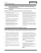
CONFIDENTIAL 1 Precautions 1-2 Servicing Precautions WARNING 1:First read the “Safety Precautions” section of this manual. If unforeseen circumstances create conflict between the servicing precautions and safety precautions, always follow the safety precautions. WARNING 2:A high voltage Micom control replaced in the wrong direction may cause excessive Xray emissions. WARNING 3:An electrolytic capacitor installed with the wrong polarity might explode. 1.
CONFIDENTIAL 2 Product Specifications 2-1 Specifications Description Item Picture Tube 17-Inch (43 cm): 16-inch (40.6 cm) viewable, Flat-face, 90˚ Deflection, 0.20 mm (Horizontal) Dot pitch, Silica coated with anti-electrostatic properties (TCO: Multilayer coating), Medium-short persistence phosphor Scanning Frequency Horizontal : 30 kHz ~ 70 kHz Vertical : 50 Hz ~ 160 Hz Display Colors Unlimited colors Maximum Resolution Horizontal : 1280 Dots Vertical : 1024 Lines Input Video Signal Analog, 0.
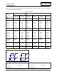
CONFIDENTIAL 2 Product Specifications 2-2 Pin Assignments Sync Type Separate Macintosh Pin No. 1 Red GND-R 2 Green Red 3 Blue H/V Sync 4 N-C Sense 0 5 DDC Return Green 6 GND-R GND-G 7 GND-G Sense 1 8 GND-B Reserved 9 N-C Blue 10 GND-Sync/Self-raster Sense 2 11 N-C GND 12 DDC Data V-Sync 13 H-Sync GND-B 14 V-Sync GND 15 DDC Clock H-Sync 5 15 Figure 2-1. Male Type 2-2 Figure 2-2.
CONFIDENTIAL 2 Product Specifications 2-3 Timing Chart This section of the service manual describes the timing that the computer industry recognizes as standard for computer-generated video signals. Table 2-1 Timing Chart Mode IBM VESA VGA2/70 Hz 720 x 400 VGA3/60 Hz 640 x 480 640/75 Hz 640 x 480 640/85 Hz 640 x 480 800/85 Hz 800 x 600 fH (kHz) 31.469 31.469 37.500 43.269 53.674 68.677 A µsec 31.777 31.778 26.667 23.111 18.631 14.561 B µsec 3.813 3.813 2.032 1.556 1.138 1.
2 Product Specifications CONFIDENTIAL Memo 2-4 AN17K*/AN17L*
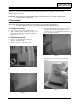
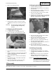
CONFIDENTIAL 3 Disassembly and Reassembly This section of the service manual describes the disassembly and reassembly procedures for the AN17K*/AN17L* monitor. WARNING: This monitor contains electrostatically sensitive devices. Use with caution when handling these components. 3-1 Disassembly Cautions:1. Disconnect the monitor from the power source before disassembly. 2. To remove the Rear Cover, you must use the special opening jig tool. 3-1-1 Before Disassembly 1. Disconnect power cord from the monitor.
CONFIDENTIAL 3 Disassembly and Reassembly 6. Remove the Shield.(TCO 99) 3-1-4 Removing the Main PCB 1. Complete all previous steps. 2. Disconnect the Degaussing Coil at CN603 on the Main PCB. 3. Disconnect all easily accessible ground wires on the PCB and Bottom Chassis. 4. Disconnect the DY connector at the CN404 connector on the Main PCB. 5. Using the jig, release the snaps (2) connecting the Front Cover and the PCB then lift up the bottom to separate the two shields. Figure 5 7.
CONFIDENTIAL 4 Alignment and Adjustments This section of the service manual explains how to make permanent adjustments to the monitor. Directions are given for adjustments using the monitor Interface Board Ver. 2.0 and software (Softjig). 4-1 Adjustment Conditions Caution: Changes made without the Softjig are saved only to the user mode settings. As such, the settings are not permanently stored and may be inadvertently deleted by the user.
CONFIDENTIAL 4 Alignment and Adjustments 4-2 Display Control Adjustments 4-2-1 HIGH VOLTAGE Signal: 1024 x 768 (68 kHz/85 Hz) Display image: Don’t care Contrast: Minimum Brightness: Minimum Limit: 26.0 kV ± 0.3 kV Measure the high voltage level at the anode cap. High voltage should be within the limit as above. 4-2-2 CENTER RASTER Adjust SW401 so that the back raster comes to the center when you apply basic mode for 17”.
CONFIDENTIAL 4 Alignment and Adjustments Use control bar after selecting “PINBALANCE” in left menu to optimize the image. Table 4-2. Other Modes Linearity: above 40 KHz(Hf) Supported Timing Mode Difference between adjacent blocks (5 %) Each block (14 %) Horizontal: 20.5~23.5 Vertical : 20.5~23.5 4:3 Horizontal: Less than 1.10 mm Vertical : Less than 1.
CONFIDENTIAL 4 Alignment and Adjustments 4-3 Color Adjustments CAUTION:Check below condition before color adjustment Video signal : Analog 0.7 Vp-p (at 75 Ω) Sync : TTL level (H, V seperate signal) * Select “Color” in Softjig menu for color adjustment. 4-3-1 Color Coordinates (Temperature) Color temperature is a measurement of the radiant energy transmitted by a color. For computer monitors, the color temperature refers to the radiant energy transmitted by white.
CONFIDENTIAL 4 Alignment and Adjustments 4-3-2 (d) WHITE BALANCE ADJUSTMENT VERIFICATION CONDITIONS Scanning frequency: Display image: X-Y Coordinates: ABL Luminance Brightness: Contrast: 68 kHz/85 Hz Back raster pattern Full White Pattern x = 0.283 ± 0.02, y = 0.298 ± 0.02 Refer to 4-3-2(c) Maximum 5 ft-L, 24 ft-L 1. Check whether the color coordinates of the back raster satisfy the above spec. If they do not, return to 4-3-2 (a) and readjust all settings. 2. Display a full white pattern. 3.
CONFIDENTIAL 4 Alignment and Adjustments PROCEDURE For trained and experienced service technicians only. Use the following procedure to correct minor color purity problems: 1. Make sure the display is not affected by external magnetic fields. 2. Make sure the spacing between the PCM assembly and the CRT stem is 29 mm ± 1 mm. 3. Display a green pattern over the entire display area. 4. Adjust the purity magnet rings on the PCM assembly to display a pure green pattern. AN17K*(Optimum setting: x = 0.276 ± 0.
CONFIDENTIAL 5 Troubleshooting 5-1 Parts Level Troubleshooting Notes: Check the following circuits. • No raster appears: Power circuit, Horizontal output circuit. • High voltage develops but no raster appears: Video output circuits. • High voltage does not develop: Horizontal output circuits. 5-1-1 No Power Supply WAVEFORMS Check and replace D601 and FH1 1 100 V (IC601, #1) Chirping noise exists? Yes Check and replace IC601. No Repeating start? Yes Check and replace D606.
CONFIDENTIAL 5 Troubleshooting 5-1-2 DPMS Failure WAVEFORMS Check signal source H/V Sync. video level. 2 100V (IC601, #1) Make No H/V Sync. (power off mode) LED blinks? No Check IC201 Pin 40. CH1 P-P = 100V CH1 RMS = 325.8 V Yes +12 V line off? No Check IC201 Pin 5/Pin 6 and Q610/Q602 operation. No Check IC201 Pin 5. Check and replace Q602 and IC201. Yes Q602 Base voltage exists? Yes 2 IC601 Pin 1 output voltage exists? No Refer to 5-1-1 No Power Supply.
CONFIDENTIAL 5 Troubleshooting 5-1-3 H_Deflection Failure 3 Does PWM output signal appear at Pin 28 (B_DRV) of IC401? No Yes Does DC 12V appear at Pin 29 of IC401? No Check 12 V line. Yes WAVEFORMS Check IC401. 3 2.00 V (IC401, #28) 4 Does Horizontal pluse signal appear at Pin 26 of IC401? No Check IC401. Yes 5 Does 110 Vp-p signal appear at Collector of Q403? No Check Q403. CH1 P-P = 2.00V CH1 RMS = 5.868V 4 2.00V (IC401, #26) Yes Check Q402, Q404 and T401. CH1 P-P = 2.00V CH1 RMS = 5.
CONFIDENTIAL 5 Troubleshooting 5-1-5 H_Lin. Failure Check and Replace T402 5-1-6 Invariable H_Size IC401 Pin 28 voltage varies with different B_DRV DAC values? No Check and replace IC401. Yes Q402 Gate output duty varies with different B_DRV DAC values? No Check some parts around Q402, IC401 Pin 14 ~ 16. 5-1-7 Abnormal H_Size IC401 Pin 24 output duty varies with different B+ offset DAC values? No WAVEFORMS Check and replace IC201.
CONFIDENTIAL 5 Troubleshooting 5-1-8 Side Pin or Trap Failure 7 IC401 Pin 24 output exists? No WAVEFORMS Check and replace IC401. 7 1.00 V (IC401, #24) Yes Refer to 5-1-7 Abnormal H_Size. CH1 P-P = 1.00V CH1 RMS = 3.008 V 5-1-9 Para. or Pin Balance Failure IC401 Pin 24 output varies with different DAC values? Yes Refer to 5-1-7 Abnormal H_Size. No Replace IC401.
CONFIDENTIAL 5 Troubleshooting 5-1-11 V Deflection Failure WAVEFORMS 13V and –13V lines are on? No Refer to 5-1-1 No Power Supply 8 500 V (IC401, #23) Yes 8 IC401 Pin 23 output exists? No Check and replace IC401. Yes 9 IC301 Pin 6 output exists? CH1 P-P = 500 V CH1 RMS = 1.425 V No Check and replace components around IC301. 9 10.0 V (IC301, #6) Yes Check DY connector connection. CH1 P-P = 10.0 V CH1 RMS = 5.
CONFIDENTIAL 5 Troubleshooting 5-1-13 High Voltage Failure WAVEFORMS 3 IC401 Pin 28 OSC pulse exists? No Check and replace IC401 and +12 V line. 3 2.00 V (IC401, #28) Yes 10 Q402 Gate driving pulse exists? No Check and replace Q401 and Q420. Yes 11 Q402 Drain pulse exists? CH1 P-P = 2.00 V CH1 RMS = 5.868 V No Check and replace Q402, L402 and D401. Check 50V Line. 10 2.00 V (Q402, Gate) Yes Done CH1 P-P = 2.00 V CH1 RMS = 7.692V 11 50.
CONFIDENTIAL 5 Troubleshooting 5-1-15 Dynamic Focus Failure 12 IC401 Pin 32 output is right? No WAVEFORMS Replace the IC401. 12 2.00 V (IC401, #32) Yes Some parts around Q551 are right? No Replace failed part. Yes 13 T502 Pin 6 input is right? CH1 P-P = 2.00V CH1 RMS = 6.124V No Check and replace C432. 13 50.0 V (T502, #6) Yes 14 T502 Pin 1 output is right? Yes Check the connection between FBT Focus pin and CRT Socket PCB. No Replace the T502. CH1 P-P = 50.0V CH1 RMS = 75.
CONFIDENTIAL 5 Troubleshooting 5-1-16 No Video WAVEFORMS Check signal cable and connection. 15 1.00V (IC101 #12,14,16) 15 IC101 Pin 12, 14 and 16 inputs are right? No Check the signal cable connection. Yes 16 IC101 Pin 18, 21 and 24 outputs are right? No Check I2C bus and +12V line. 16 1.00V (IC101 #18,21,24) Yes 17 IC102 Pin 9, 10 and 11 outputs are right? CH1 P-P = 1.00V CH1 RMS = 2.452V No Check +12V, +80V line. Check and replace IC102. No Check +80V line. Check and replace IC104.
CONFIDENTIAL 5 Troubleshooting 5-1-17 Micom Failure IC201 Pin 11 input voltage is 5V? No WAVEFORMS Check IC604. 18 1.00 V (IC201, #13, 14) Yes 18 IC201 Pin 13 and 14 inputs are right? No Check C202, C203 and X201. Yes CH1 P-P = 1.00 V CH1 RMS = 2.108V IC201 Pin 18 input is right? No Check and replace IC201 and R206. Yes All in/output values are right? No Replace IC201.
CONFIDENTIAL 5 Troubleshooting 5-1-18 OSD Failure Check CN102 and connector Ass’y. WAVEFORMS 19 1.00 V (IC101, #32) Yes 19 IC101 Pin 32 input is right? No Check and replace R117, C117 and IC101. Yes 20 IC101 Pin 1 input is right? No Check CN102 Pin 8. CH1 P-P = 1.00V CH1 RMS = 4.516V 20 1.00 V (IC101, #1) Yes IC101 Pin 29 and 30 inputs are right? No Check IC201 Pin 41 and 42. Yes 21 IC101 Pin 18, 21 and 24 outputs are right? No CH1 P-P = 1.00V CH1 RMS = 5.024V Check and replace IC101.
CONFIDENTIAL 5 Troubleshooting 5-1-19 User Control Failure Does the DC level change at Pin 38 of IC201 when you push the S/W button? No Check the button. (SW201 ~ SW204) Yes Check IC201. 5-1-20 Degaussing Failure Check degaussing connector. RL601 operation is right? Yes Check D-coil and TH601. No Q601 base input is right? Yes Check and replace Q601. No IC201 Pin 4 output is right? No Check and replace IC201.
CONFIDENTIAL 5 Troubleshooting 5-2 General Troubleshooting 5-2-1 No Picture LED blinks? Yes Refer to 5-2-2 Shut down. No LED is green color? Yes Check Micom. No Check G2 voltage, high voltage and R, G, B cathode voltage. 5-2-2 Shut Down Blinking LED’s? No Check power supply. Yes Scan failure? Yes Check horizontal, vertical deflection system and check power supply secondary voltages. No Video failure? Yes Check Video board. No Check and replace IC201.
CONFIDENTIAL 5 Troubleshooting 5-2-3 Missing Color WAVEFORMS Proper Video levels are on CN101 (D-Sub) Pin 1, 3 and 5? No Check signal generator. 22 10.0 V (R,G,B, Video) Yes 22 Proper Video signal to all cathodes? No Refer to 5-1-16 No Video. Yes Proper DC voltage to all cathodes? CH1 P-P = 10.0V CH1 RMS = 17.02V No Check IC101 Pin 17, 20 and 23. Check IC104. Yes G2 voltage is right? No Check T501 and D502, D512. Yes Heater voltage is right? No Check D608, Q604 and T601.
CONFIDENTIAL 5 Troubleshooting 5-2-4 Visible Retrace WAVEFORMS Check white balance adjustment. 23 5.00V (Q303, Collector) G2 voltage is right? No Check D502, D512. Yes Blank pulse at Pin 3 of IC401? No Check IC401. 24 20.00V (CRT Socket, G1) Yes 23 V_FLB pulse at Collector of Q303? CH1 P-P = 5.00V CH1 RMS = 28.33V No Check Q303. Yes 24 Valid the Vertical pulse on CRT Socket G1? No Check CN102 and CN201. CH1 P-P = 20.0V CH1 RMS = 66.
CONFIDENTIAL 5 Troubleshooting 5-2-5 Unsynchronized Image Check input signals Pin 2 and 3 of CN202. Signals are right? No Check Video Cable Yes Signals at Pin 28 and 29 of IC201 are right? No Check IC201. Yes Signals at Pin 1 and 2 of IC401 are right? No Check IC401 Yes Check circuits on Main board.
CONFIDENTIAL 5 Troubleshooting 5-2-6 Misconvergence Adjust convergence. Convergence is now within spec.? Yes Done No Readjust convergence. Convergence is now within spec.? Yes Done No Change CRT and readjust convergence.
CONFIDENTIAL 5 Troubleshooting 5-2-7 Poor Focus Adjust focus VR of FBT. Improved focus? Yes Align monitor and check for focus change. No Refer to 5-1-15 Dynamic Focus Failure. No Check focus leads from FBT to CRT Socket. Check CRT Socket. Dynamic focus circuit is right? Yes Replace the CRT and verify focus. 5-2-8 Purity Failure Degause Purity is correct? Yes Done No Degaussing circuit is correct? No Refer to 5-1-20 Degaussing Failure. Yes Replace CRT and verify purity.
CONFIDENTIAL 6 Exploded View and Parts List 6-1-1 AN17KS AN17K*/AN17L* 6-1
CONFIDENTIAL 6 Exploded View & Parts List 6-1-2 AN17KS Front 7 8 6 4 3 5 9 1 2 6-2 AN17K*/AN17L*
6 Exploded View & Parts List CONFIDENTIAL 6-2-1 AN17KT AN17K*/AN17L* 6-3
CONFIDENTIAL 6 Exploded View & Parts List 6-2-2 AN17KT Front 5 9 8 10 6 4 1 3 2 6-4 AN17K*/AN17L*
6 Exploded View & Parts List CONFIDENTIAL 6-3-1 AN17LS AN17K*/AN17L* 6-5
CONFIDENTIAL 6 Exploded View & Parts List 6-3-2 AN17LS Front 5 9 10 7 8 4 1 3 2 6-6 AN17K*/AN17L*
6 Exploded View & Parts List CONFIDENTIAL 6-4-1 AN17LT AN17K*/AN17L* 6-7
CONFIDENTIAL 6 Exploded View & Parts List 6-4-2 AN17LT Front 5 9 10 8 6 4 1 3 2 6-8 AN17K*/AN17L*
CONFIDENTIAL 7 Electrical Parts List 7-1-1 AN17K* Main PCB Parts Loc. No. AN_LABEL C409 C430 C601 C602 C608 CIS1 CIS11 CIS12 CIS13 CIS14 CIS15 CIS16 CIS2 CIS3 CIS4 CIS8 CLAMP1 CLAMP2 CN201 CN202 CN404 CN501_G2 CN601 CN604 D406 D409 D601 D608 D609 D611 FUSE IC201_SOCK IC401 IC605 L401 L402 L403 L601 OP201 Q409 Q410 RL601 S_CABLE SW401 SW601 T401 T402 T501 T502 T601 T602 AN17K*/AN17L* Code No.
CONFIDENTIAL 7 Electrical Parts List Loc. No. Code No. Description Specification Remarks TH601 TH602 1404-001264 1404-001020 THERMISTOR-PTC THERMISTOR-NTC 4.
CONFIDENTIAL 7 Electrical Parts List Loc. No. C413 C414 C415 C416 C419 C420 C421 C423 C425 C426 C427 C429 C431 C432 C433 C436 C440 C461 C462 C463 C501 C502 C503 C504 C505 C508 C509 C510 C512 C513 C514 C515 C516 C517 C518 C541 C551 C552 C553 C603 C604 C606 C607 C609 C610 C611 C612 C613 C614 C615 C616 C617 C618 C619 C620 AN17K*/AN17L* Code No.
CONFIDENTIAL 7 Electrical Parts List Loc. No. C621 C622 C623 C624 C625 C626 C627 C628 C629 C630 C631 C633 C634 C635 C636 C643 C649 CIS5 CIS6 CN304 CN501 CN603 D201 D301 D302 D303 D401 D402 D403 D404 D405 D407 D410 D411 D412 D413 D414 D415 D416 D419 D420 D421 D501 D502 D503 D504 D505 D506 D508 D509 D510 D511 D512 D513 D514 7-4 Code No.
CONFIDENTIAL 7 Electrical Parts List Loc. No. D602 D604 D605 D606 D607 D610 D612 D613 D615 D616 D625 D626 D628 D629 D630 EY301 EY302 EY401 EY444 EY445 EY501 EY502 EY503 EY504 EY505 EY506 EY507 EY508 EY509 EY510 EY601 EY602 EY603 EY604 EY605 EY606 EY607 EY608 EY609 EY610 GT603 GT604 IC202 IC602 IC604 JP_DHHS JP1 JP10 JP11 JP12 JP14 JP15 JP16 JP17 JP18 AN17K*/AN17L* Code No.
CONFIDENTIAL 7 Electrical Parts List Loc. No. JP19 JP2 JP20 JP21 JP22 JP225 JP23 JP233 JP239 JP24 JP240 JP248 JP251 JP252 JP258 JP262 JP264 JP265 JP266 JP269 JP27 JP270 JP29 JP3 JP30 JP31 JP32 JP33 JP35 JP36 JP37 JP38 JP39 JP4 JP40 JP41 JP42 JP43 JP44 JP45 JP46 JP47 JP48 JP49 JP5 JP50 JP51 JP52 JP53 JP54 JP55 JP56 JP57 JP59 JP6 7-6 Code No.
CONFIDENTIAL 7 Electrical Parts List Loc. No. JP60 JP61 JP62 JP63 JP64 JP65 JP66 JP67 JP68 JP69 JP7 JP70 JP71 JP73 JP74 JP75 JP76 JP78 JP79 JP8 JP80 JP81 JP84 JP85 JP86 JP87 JP9 MP1.0_MAIN Q301 Q302 Q303 Q401 Q403 Q405 Q406 Q407 Q414 Q415 Q416 Q420 Q502 Q551 Q601 Q602 Q604 Q609 Q610 Q611 Q613 Q614 R200 R201 R202 R203 R204 AN17K*/AN17L* Code No.
CONFIDENTIAL 7 Electrical Parts List Loc. No. R205 R206 R207 R208 R209 R212 R213 R214 R215 R216 R217 R218 R219 R220 R221 R222 R223 R224 R225 R229 R235 R236 R301 R302 R304 R306 R307 R308 R309 R310 R311 R315 R316 R317 R320 R321 R322 R323 R324 R325 R326 R327 R328 R340 R401 R404 R405 R406 R407 R408 R411 R412 R413 R415 R416 7-8 Code No.
CONFIDENTIAL 7 Electrical Parts List Loc. No. R417 R418 R419 R420 R423 R424 R425 R426 R427 R428 R429 R430 R431 R432 R434 R435 R436 R437 R438 R439 R443 R444 R445 R446 R450 R451 R452 R453 R454 R455 R461 R500 R501 R502 R504 R505 R506 R507 R508 R509 R510 R511 R513 R514 R515 R516 R517 R518 R520 R522 R523 R524 R526 R529 R530 AN17K*/AN17L* Code No.
CONFIDENTIAL 7 Electrical Parts List Loc. No. R531 R551 R552 R553 R554 R555 R556 R557 R558 R600 R601 R602 R603 R604 R605 R606 R607 R608 R609 R610 R611 R612 R613 R614 R615 R616 R617 R618 R619 R620 R621 R622 R623 R624 R625 R627 R630 R631 R632 R634 R635 R663 R664 R666 R668 R671 SK501 TP401 TP402 TP501 X201 ZD201 ZD202 ZD203 ZD204 7-10 Code No.
CONFIDENTIAL 7 Electrical Parts List Loc. No. Code No. Description Specification Remarks ZD205 ZD206 ZD207 ZD209 ZD210 ZD211 ZD502 0403-000361 0403-000361 0403-000361 0403-000348 0403-001068 0403-000361 0403-000355 DIODE-ZENER DIODE-ZENER DIODE-ZENER DIODE-ZENER DIODE-ZENER DIODE-ZENER DIODE-ZENER UZ6.2BSB,6.2V,5.99-6.24V,500mW UZ6.2BSB,6.2V,5.99-6.24V,500mW UZ6.2BSB,6.2V,5.99-6.24V,500mW UZ36B,36V,33-39V,500mW,DO-35,T UZ4.7BSA,4.7V,4.47-4.65V,500mW UZ6.2BSB,6.2V,5.99-6.24V,500mW UZ5.1BSB,4.97-5.
CONFIDENTIAL 7 Electrical Parts List 7-1-2 AN17K* Video PCB Parts Loc. No. Code No. Description Specification Remarks 17_NOR CIS1 CIS2 CIS3 CIS4 CIS8 CN101 CN102 IC101 SH/VID+H/S V_CLAMP1 VIDEO PCB BH94-00824A 3704-001170 0202-001044 0204-001527 0202-001222 0204-001095 BH63-00055A 3711-004228 BH39-00015A 1201-001947 6003-000010 6502-000001 ASSY PCB VIDEO SOCKET-CRT SOLDER-WIRE.
CONFIDENTIAL 7 Electrical Parts List Loc. No. CG08 CIS5 CIS6 CIS7 CR01 CR02 CR04 CR06 CR08 DB01 DB02 DB03 DB04 DB05 DG01 DG02 DG03 DG04 DG05 DR01 DR02 DR03 DR04 DR05 EY1 EY3 EY4 EY5 EY6 G2 GND IC104 J1 J10 J11 J12 J13 J14 J15 J2 J3 J4 J5 J6 J7 J8 J9 L101 L103 LB01 LG01 LR01 MP1.0_VID R101 R102 AN17K*/AN17L* Code No.
CONFIDENTIAL 7 Electrical Parts List Loc. No. Code No.
CONFIDENTIAL 7 Electrical Parts List 7-1-3 AN17K* Others Loc. No. Code No. Description Specification Remarks CIS CIS CIS CIS CIS CIS CIS CIS CIS BH90-00257A BH75-00274A BH60-00030A BH61-40002A BH63-30103A BH68-20366A BH68-70306A BH69-30348C BH72-00277A BH72-60740A ASSY STAND UNIT-STAND FASTENER-BAND FOOT-RUBBER FELT-STAND LABEL-MARK STAND CARD-STAND BAG-PE STAND TOP STAND BASE-USB PN17HT,ABS HB,IV16,W/W PN15VT,-,ABS HB,-,IV16,-,PN17LT,ST+PVC,P0.
CONFIDENTIAL 7 Electrical Parts List Loc. No. Code No. Description Specification Remarks - BH91-00796A ASSY CHASSIS AN17KS BOX BOX BH92-00869A BH68-00329C BH69-00488A ASSY BOX LABEL BAR CODE BOX AN17KS -,ALL,TCO99,DOMESTIC,ART-PAPER 90G,-,WHT,BLACK,-,-,S/M753DF,W/W,CB-SW4,YEL,A-1,L609*W566*H440 SNA SNA SNA LABEL BH92-00870A BH68-00496B ASSY LABEL LABEL RATING AN17KS AN17KS@EDC,SYNC,PE,T0.
CONFIDENTIAL 7 Electrical Parts List 7-2-1 AN17L* Main PCB Parts Loc. No. AN_LABEL C409 C430 C601 C602 C608 CIS1 CIS11 CIS13 CIS14 CIS15 CIS16 CIS17 CIS2 CIS3 CIS4 CIS8 CLAMP1 CLAMP2 CN201 CN202 CN404 CN501_G2 CN502_W CN601 CN604 D406 D409 D601 D608 D609 D611 FBT+H/S FUSE IC201_SOCK IC401 IC605 L401 L402 L403 L601 OP201 Q409 Q410 RL601 S/BTM+PCB S_CABLE SH/BT+AC/S SH/BT+SH/L SH/BT+VI/G SH/VID+H/S SW401 SW601 T401 AN17K*/AN17L* Code No.
CONFIDENTIAL 7 Electrical Parts List Loc. No. Code No. Description Specification Remarks T402 T501 T502 T601 T602 TH601 TH602 BH27-00132A BH26-00143A BH26-00112A BH26-00142A BH26-00141A 1404-001264 1404-001020 COIL LINEARITY TRANS FBT TRANS-FOCUS TRANS SWITCHING TRANS-SYNC THERMISTOR-PTC THERMISTOR-NTC 4.4UH,4.4UH,DR12X15 C:4.5,7MM,15X15X35MM,12X8T,21.0TS,TR,12%,0.03OHM FQM17B015,AN17L,1.21MH,SM19C,FUR3757SU,0.510OHM,153.7V,13P,-10 ~60,BK,27.0KV EE-1916,PN17L,5P,1.7mH MIN,-,-,90.0mH MIN,-,-,0.
CONFIDENTIAL 7 Electrical Parts List Loc. No. C407 C408 C410 C411 C412 C413 C414 C415 C416 C419 C420 C421 C423 C425 C426 C427 C429 C431 C432 C433 C436 C440 C461 C462 C463 C501 C502 C503 C504 C505 C508 C509 C510 C512 C513 C514 C515 C516 C517 C541 C551 C552 C553 C603 C604 C606 C607 C609 C610 C611 C612 C613 C614 C615 C616 AN17K*/AN17L* Code No.
CONFIDENTIAL 7 Electrical Parts List Loc. No. C617 C618 C619 C620 C621 C622 C623 C624 C625 C626 C627 C628 C629 C630 C631 C633 C634 C635 C636 C643 C649 CIS5 CIS6 CN304 CN501 CN603 D201 D301 D302 D303 D401 D402 D403 D404 D405 D407 D410 D411 D412 D413 D414 D415 D416 D419 D420 D421 D501 D502 D503 D504 D505 D506 D508 D509 D510 7-20 Code No.
CONFIDENTIAL 7 Electrical Parts List Loc. No. D511 D512 D513 D602 D604 D605 D606 D607 D610 D612 D613 D615 D616 D625 D626 D628 D629 D630 EY301 EY302 EY401 EY444 EY445 EY501 EY502 EY503 EY504 EY505 EY506 EY507 EY508 EY509 EY510 EY601 EY602 EY603 EY604 EY605 EY606 EY607 EY608 EY609 EY610 GT603 GT604 IC202 IC602 IC604 JP_DHHS JP1 JP10 JP11 JP12 JP13 JP14 AN17K*/AN17L* Code No.
CONFIDENTIAL 7 Electrical Parts List Loc. No. JP15 JP16 JP17 JP18 JP189 JP19 JP2 JP20 JP21 JP22 JP225 JP23 JP233 JP239 JP24 JP248 JP251 JP252 JP258 JP262 JP264 JP265 JP266 JP269 JP27 JP270 JP29 JP3 JP30 JP31 JP32 JP33 JP35 JP36 JP37 JP38 JP39 JP4 JP40 JP41 JP42 JP43 JP44 JP45 JP46 JP47 JP48 JP49 JP5 JP50 JP51 JP52 JP53 JP54 JP55 7-22 Code No.
CONFIDENTIAL 7 Electrical Parts List Loc. No. JP56 JP57 JP59 JP6 JP60 JP61 JP62 JP63 JP64 JP65 JP66 JP67 JP68 JP69 JP7 JP70 JP71 JP73 JP74 JP75 JP76 JP78 JP79 JP8 JP80 JP81 JP84 JP85 JP86 JP87 JP9 MP1.0_MAIN Q301 Q302 Q303 Q401 Q403 Q405 Q406 Q407 Q414 Q415 Q416 Q420 Q502 Q551 Q601 Q602 Q604 Q609 Q610 Q611 Q613 Q614 R200 AN17K*/AN17L* Code No.
CONFIDENTIAL 7 Electrical Parts List Loc. No. R201 R202 R203 R204 R205 R206 R207 R208 R209 R212 R213 R214 R215 R216 R217 R218 R220 R221 R222 R223 R224 R225 R229 R235 R236 R301 R302 R304 R306 R307 R308 R309 R310 R311 R315 R316 R317 R320 R321 R322 R323 R324 R325 R326 R327 R328 R340 R401 R404 R405 R406 R407 R408 R411 R412 7-24 Code No.
CONFIDENTIAL 7 Electrical Parts List Loc. No. R413 R415 R416 R417 R418 R419 R420 R423 R424 R425 R426 R427 R428 R429 R430 R431 R432 R434 R435 R436 R437 R438 R439 R443 R444 R445 R446 R450 R451 R452 R453 R454 R455 R461 R500 R501 R502 R504 R505 R506 R507 R508 R509 R510 R511 R513 R514 R515 R516 R518 R520 R522 R523 R524 R526 AN17K*/AN17L* Code No.
CONFIDENTIAL 7 Electrical Parts List Loc. No. R529 R530 R531 R551 R552 R553 R554 R555 R556 R557 R558 R600 R601 R602 R603 R604 R605 R606 R607 R608 R609 R610 R611 R612 R613 R614 R615 R616 R617 R618 R619 R620 R621 R622 R623 R624 R625 R627 R630 R631 R632 R634 R635 R663 R664 R666 R668 R671 SK501 TP401 TP402 TP501 X201 ZD201 ZD202 7-26 Code No.
CONFIDENTIAL 7 Electrical Parts List Loc. No. Code No. Description Specification Remarks ZD203 ZD204 ZD205 ZD206 ZD207 ZD209 ZD210 ZD211 ZD502 0403-000361 0403-000361 0403-000361 0403-000361 0403-000361 0403-000348 0403-001068 0403-000361 0403-000355 DIODE-ZENER DIODE-ZENER DIODE-ZENER DIODE-ZENER DIODE-ZENER DIODE-ZENER DIODE-ZENER DIODE-ZENER DIODE-ZENER UZ6.2BSB,6.2V,5.99-6.24V,500mW UZ6.2BSB,6.2V,5.99-6.24V,500mW UZ6.2BSB,6.2V,5.99-6.24V,500mW UZ6.2BSB,6.2V,5.99-6.24V,500mW UZ6.2BSB,6.2V,5.
CONFIDENTIAL 7 Electrical Parts List 7-2-2 AN17L* Video Loc. No. Code No. Description Specification Remarks 17_NOR CIS CIS1 CIS2 CIS3 CIS4 CIS8 CN101 CN102 IC101 SH/VID1 SH/VID2 SH/VID3 V_CLAMP1 V_CLAMP2 BH94-00824D 3704-001170 BH63-00056A 0202-001044 0204-001527 0202-001222 0204-001095 BH63-00055A 3711-004228 BH39-00015A 1201-001947 BH39-00134A BH39-00412A BH39-00153A 6502-000001 6502-000127 ASSY PCB VIDEO SOCKET-CRT SHIELD-VIDEO CAP SOLDER-WIRE.
CONFIDENTIAL 7 Electrical Parts List Loc. No. CG04 CG06 CG07 CG08 CIS5 CIS6 CIS7 CR01 CR02 CR04 CR06 CR07 CR08 DB01 DB02 DB03 DB04 DB05 DG01 DG02 DG03 DG04 DG05 DR01 DR02 DR03 DR04 DR05 EY1 EY3 EY4 EY5 EY6 G2 GND IC104 J1 J10 J11 J12 J13 J14 J15 J2 J3 J4 J5 J6 J7 J8 J9 L101 L103 LB01 LG01 AN17K*/AN17L* Code No.
CONFIDENTIAL 7 Electrical Parts List Loc. No. Code No. Description Specification Remarks LR01 MP1.
CONFIDENTIAL 7 Electrical Parts List 7-2-3 AN17L* Others Loc. No. Code No.
CONFIDENTIAL 7 Electrical Parts List Loc. No. Code No. Description Specification Remarks CIS CIS CIS CIS CIS CIS CIS CIS BH92-00509A 0203-001100 0203-001159 BH69-00260A BH69-00359A BH69-30002C BH69-30348A BH69-30360A BH69-40380A ASSY P/MATERIAL TAPE-OPP MASKING TAPE-FILAMENT BAG AIR CUSHION-L/R(S) BAG-PE BAG-PE BAG-AIR PACKING-PAD AQ17LS OPP/W75/CLR,T0.05,W75,L800000,CLR #8915,T0.15,W12,L55000,CLR DP17L,PE,0.2,1800,1000,NATURAL,AQ17LS,EPS M50,-,-,-,-,-,-,LDPE,T0.05,W2400,NO_PRINT HDPE,T0.
VIDEO INPUT SIGNAL VIDEO PRE-AMP + OSD IC101 SID2551 OR SID2552 H/V SYNC VIDEO OUTPUT IC102 STV9556 RGB SOCKET RGB - CUTOFF IC104 LM2480 F O C U S G1 HEATER MAIN BOARD H-SYNC, V-SYNC STV6888 KA2142 H-SYNC1 V-SYNC1 E/W_OUT UP, DOWN BRIGHTNISS CONTRASTER PIN, TRAP SIZE, POSI, DEGA. HORZ./VER. PROCESSOR IC401 MCU IC201 VER. DY CN401 HORZ. DRIVE Q403 H. D. T T401 VERTICAL FOCUS HOR. OUT Q404 HOR. DY CN401 J6810 LED POWER REG. FROM MCU S-COR. FBT T501 FROM IC401 EPROM IC202 24LC04 VER.
8 Block Diagrams CONFIDENTIAL Memo 8-2 AN17K*/AN17L*
CONFIDENTIAL 9 Wiring Diagram MAIN PCB CRT SOCKET PCB CRT SOCKET FOCUS1 (WHT) FOCUS2 (RED) G2 H+ (RED) H+ NC (BLUE) H(YEL) V+ H– (BROWN)VNC 1 1 2 3 4 2 3 4 H+ H– V+ V– H+ NC H– NC CN501 FBT CN404 CN102 CN201 70 V GND 6.3 V G1 GND 12 V VS-OUT ACL IICDATA IICCLK HS-OUT OSD-5V AFC DEGAUSSING COIL AC AC 1 1 2 2 AC INPUT AC AC 1 AC INPUT 2 NC 3 AC INPUT FOCUS (WHT) CN603 1 1 2 3 4 5 6 7 8 9 2 3 4 5 6 7 8 9 10 11 12 13 10 11 12 13 14 CN601 70 V GND 6.
9 PCB Diagrams CONFIDENTIAL Memo 9-2 AN17K*/AN17L*
CONFIDENTIAL 10 Schematic Diagrams 10-1 Main Part Schematic Diagram 13V_1 6.3V_1 B 12V CN202 slcon7p 1 BD301 BFS3557AOLS1 R326 1K 1/4W HS_IN R671 100 1/6W 3 VS_IN C B 4 DDCDATA Q301 2N3904 CN304 slcon3p 5V C DDCCLK E B 3 Q302 2N3906 C C649 100nF 50V 2 1 23 MO FST:3.3Kohm 50V ZD202 UZ6.2BSB ZD203 UZ6.2BSB ZD204 UZ6.2BSB D618 UZ6.2BSB TILT R320 10K 1/8W 6.
CONFIDENTIAL 10 Schematic Diagrams 1 100 V (IC601, #1) 2 100V (IC601, #1) 3 2.00 V (IC401, #28) 4 2.00V (IC401, #26) 5 20.0 V (Q403, Collector) CH1 P-P = 100 V CH1 RMS = 350.2 V CH1 P-P = 100V CH1 RMS = 325.8 V CH1 P-P = 2.00V CH1 RMS = 5.868V CH1 P-P = 2.00V CH1 RMS = 5.868V CH1 P-P = 20.0 V CH1 RMS = 46.80V 6 200 V (Q404, Collector) 7 1.00 V (IC401, #24) 8 500 V (IC401, #23) 9 10.0 V (IC301, #6) 10 2.00 V (Q402, Gate) CH1 P-P = 200V CH1 RMS = 387.2V CH1 P-P = 1.00V CH1 RMS = 3.
CONFIDENTIAL 10 Schematic Diagrams 10-2 Video Part Schematic Diagram 5V 12V 12_1V BD105 B C152 100nF 50V MO C151 100nF 50V MO C103 470uF 16V 12V BD103 1.2UH,3.5X5.7MM B 70V B BD102 1.2UH,3.5*5.7MM R124 L103 0.
CONFIDENTIAL 10 Schematic Diagrams 15 1.00V (IC101 #12,14,16) CH1 P-P = 1.00V CH1 RMS = 2.452V 21 1.00 V (IC101, #18,21,24) CH1 P-P = 1.00V CH1 RMS = 2.580V 10-4 16 1.00V (IC101 #18,21,24) CH1 P-P = 1.00V CH1 RMS = 2.792V 22 10.0 V (R,G,B, Video) CH1 P-P = 10.0V CH1 RMS = 17.02V 17 20.0V (IC102, #9, 10, 11) CH1 P-P = 20.0V CH1 RMS = 40.52V 19 1.00 V (IC101, #32) CH1 P-P = 1.00V CH1 RMS = 4.516V 20 1.00 V (IC101, #1) CH1 P-P = 1.00V CH1 RMS = 5.024V 24 20.00V (CRT Socket, G1) CH1 P-P = 20.
Samsung Electronics Co.,Ltd. 416, Maetan-3Dong, Paldal-Gu, Suwon City, Kyungki-Do, Korea. Printed in Korea 442-742 P/N : BH82-00005C-00 http://www.samsungmonitor.com (SyncMaster Worldwide) http://www.samsung-monitor.com (SyncMaster USA) http://www.sec.co.