
Product specifications


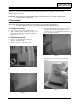

6. Remove the Shield.(TCO 99)
7. Using pinch-nose pliers or ling-nose pliers,
carefully disconnect the Anode Cap from the
CRT.
Warning: Do not touch the Anode contact
on the CRT (High Voltage may
remain).
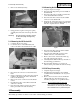
3-1-3 Removing the CRT Socket PCB
1. Complete all previous steps.
2. Loosen the screw on the CRT Neck and
remove the CRT Socket PCB from the CRT.
3. Disconnect all connectors on the CRT Socket
PCB.
4. Using a soldering iron, disconnect the Ground
(GND) on the back of the Video Shield and
remove the Shield Cap.
5. Remove the screw on the front of the Shield
Socket.
6. Desolder the 4 tabs on the CRT Socket PCB
and remove Shield.
7. Place the Video PCB on a flat, level surface
that is protected from static electricity.
3-1-4 Removing the Main PCB
1. Complete all previous steps.
2. Disconnect the Degaussing Coil at CN603 on
the Main PCB.
3. Disconnect all easily accessible ground wires
on the PCB and Bottom Chassis.
4. Disconnect the DY connector at the CN404
connector on the Main PCB.
5. Using the jig, release the snaps (2) connecting
the Front Cover and the PCB then lift up the
bottom to separate the two shields.
6. Disconnect the tilt connector at the CN304
connector on the Main PCB.
7. Disconnect the Sub PCB connector at the
CN604 connector on the Main PCB.
8. Remove the screws on the back and along
each side of the bottom chassis.
9. Carefully lift the Main PCB Assy and remove
the remaining ground wires.
10. Place the Main PCB Assy on a flat, level
surface that is protected from static electricity.
3-1-5 CRT Assy Disassembly
1. Complete all previous steps.
2. Straighten the Degaussing Coil Assembly
coated metal ties and lift the Coil Assy from
the CRT.
3. Remove the four corner screws and lift the
CRT up and away from the Front Cover
Assembly and place it on a padded surface.
Caution: Do not lift the CRT by the neck.
If you will be returning this CRT to
the monitor, be sure to place the CRT
face downward on a protective pad.
3 Disassembly and Reassembly
3-2 AN17K*/AN17L*
CONFIDENTIAL
3-2 Reassembly
Reassembly procedures are in the reverse order of disassembly procedures.
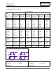
Figure 6
Figure 7
Figure 5