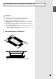
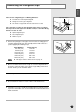
Cooling only AVMDH052CA0 AVMDH072CA0 AVMDH052EA(B)0 AVMDH070EA(B)0 AVMDC052CA0 AVMDC072CA0 AVMDC052EA(B)0 AVMDC070EA(B)0 ENGLISH RUSSIAN E§§HNIKA ™‡ÛÙËÌ· ∫ÏÈÌ·ÙÈÛÌÔ‡ ëËÒÚÂÏÌ˚È ÇÓÁ‰Û¯Ì˚È äÓ̉ˈËÓÌ DEUTSCH System Air Conditioner Aire acondicionado sistemático Climatiseur numérique multifonctionnel Sistema Aria Condizionata Sistema Ar Condicionado Klimaanlage System PORTUGUÊS ITALIANO Heat pump ESPAÑOL E°XEIPI¢IO E°KATA™TA™H™ àçëíêìäñàü èé ìëíÄçéÇäÖ FRANÇAIS INSTALLATION MANUAL MANUAL DE INSTAL
Contents Chapter Chapter DU C T(L O W SILHOUETTE) IN S TALLATION ■ Preparation for Installation . . . . . . . . . . . . . . . . . . . . . . . . . . . . . . . 4 ■ Deciding on Where to Install the Indoor Unit . . . . . . . . . . . . . . . . . 5 ■ Indoor Unit Installation . . . . . . . . . . . . . . . . . . . . . . . . . . . . . . . . . . 7 ■ Purging the Unit . . . . . . . . . . . . . . . . . . . . . . . . . . . . . . . . . . . . . . . 8 ■ Connecting the Refrigerant Pipe . . . . . . . . . . . . . .
ENGLISH Chapter DUCT(LOW SILHOUETTE) INSTALLATION ■ Preparation for Installation . . . . . . . . . . . . . . . . 4 ■ Deciding on Where to Install the Indoor Unit . . . 5 ■ Indoor Unit Installation . . . . . . . . . . . . . . . . . . . . 7 ■ Purging the Unit . . . . . . . . . . . . . . . . . . . . . . . . 8 ■ Connecting the Refrigerant Pipe . . . . . . . . . . . . 9 ■ Cutting/Flaring the Pipes . . . . . . . . . . . . . . . . . 10 ■ Performing Leak Test & Insulation . . . . . . . . . .
Preparation for Installation When deciding on the location of the air conditioner with the owner, the following restrictions must be taken into account. General Do NOT install the air conditioner in a location where it will come into contact with the following elements: ◆ ◆ ◆ ◆ ◆ Combustible gases Saline air Machine oil Sulphide gas Special environmental conditions If you must install the unit in such conditions, first consult your dealer.
ENGLISH Deciding on Where to Install the Indoor Unit Indoor Unit ◆ ◆ ◆ ◆ There must be no obstacles near the air inlet and outlet. Install the indoor unit on a ceiling that can support its weight. Maintain sufficient clearance around the indoor unit. Make sure that the water dripping from the drain hose runs away correctly and safely. ◆ The indoor unit must be installed in this way, that they are out of public access.
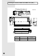
Deciding on Where to Install the Indoor Unit (cont.) Drawing of the indoor unit Unit : mm No. E-6 Name Description 1 Liquid pipe connection ø9.52 Flare 2 Gas pipe connection ø15.
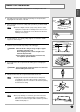
Indoor Unit Installation ENGLISH It is recommended to install the refnet joint before installing the indoor unit. 1 Carefully remove the indoor unit from the packing case and pull out the shipping block on the motor of the unit. 2 Place the pattern sheet on the ceiling at the spot where you want to install the indoor unit. Note ◆ Since the diagram is made of paper, it may shrink or stretch slightly due to temperature or humidity.
Purging the unit On delivery, the indoor unit is loaded with refrigerant gas. All this gas must therefore be purged before connecting the assembly piping. To purge the inert gas, proceed as follows. Unscrew the pinch pipe at the end of each refrigerant pipe. Result: Note E-8 All inert gas escapes from the indoor unit. ◆ To prevent dirt or foreign objects from getting into the pipes during installation, do NOT remove the pinch pipe completely until you are ready to connect the piping.
ENGLISH Connecting the Refrigerant Pipe There are two refrigerant pipes of differing diameters: ◆ A smaller one for the liquid refrigerant ◆ A larger one for the gas refrigerant ◆ The inside of copper tube must be clean & has no dust. The connection procedure for the refrigerant pipes varies according to the exit position of the pipes from the indoor unit, as seen when facing the indoor in the “A” side.
Cutting/Flaring the Pipes 1 Make sure that you have the required tools available (pipe cutter, reamer, flaring tool and pipe holder). 2 If you wish to shorten the pipes, cut it with a pipe cutter, taking care to ensure that the cut edge remains at a 90° angle with the side of the pipe. Refer to the illustrations below for examples of edges cut correctly and incorrectly. O 90 Oblique Rough Burr 3 To prevent any gas from leaking out, remove all burrs at the cut edge of the pipe, using a reamer.
ENGLISH Performing Leak Test & Insulation Leak Test To check for gas leaks on the indoor unit, check the connection part of each refrigerant pipe by using a leak detector. Insulation Once you have checked that there are no leaks in the system, you can insulate the piping and hose. 1 No gap To avoid condensation problems, place T13.0 or thicker Acrylonitrile Butadien Rubber separately around each refrigerant pipe. Note ◆ Always make the seam of pipes face upwards. NBR(T13.
Drain Hose Installation Care must be taken when installing the drain hose for the indoor unit to ensure that any condensate water is correctly drained outside. The drain hose can be installed to the right or left side of the base pan. 1 Remove the rubber cap located on the side of the base pan depending on the situation. 2 Install the drain hose so that its length can be as short as possible.
ENGLISH Testing the drainage Prepare a little water about 5 liter. 1 Pour water into the base pan in the indoor unit as shown in figure. 2 Confirm that the water flows out through the drain hose.
Connecting the Connection Cord The indoor unit is powered from the outdoor unit via the connection cord. 1 Remove the screw on the electrical component box and remove the cover plate. 2 Route the connection cord through the side of the indoor unit and connect the cable to terminals; refer to the figure below. 3 Route the other end of the cable to the outdoor unit through the ceiling & the hole on the wall. 4 Reassemble the electrical component box cover, carefully tightening the screw.
ENGLISH Increasing Fan Speed If external static pressure is too great(due to long extension of ducts, for example), the air flow volume may drop too low at each air outlet. This problem can be solved by increasing the fan speed using the following procedure. 1 Remove the screw on the electrical component box and remove the cover plate. 2 Adjust the DIP switch(SW03) on the main PCB to the “OFF” position. Switch No.
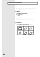
Assigning Address to Indoor Unit 1 Before installing the indoor unit, assign an address to the indoor unit according to the air conditioning system plan. 2 The address of the indoor unit is assigned by adjusting MAIN(SW02) and RMC(SW01) rotary switches. K1 K2 K3 K4 SW03 K5 K6 K7 K8 SW04 K9 K10 K11 K12 SW05 SW02 MAIN SW01 RMC 3 The MAIN address is for communication between the indoor unit and the outdoor unit. Therefore, you must set it to operate the air conditioner properly.
ENGLISH Additional Functions Compensation for lost temperature in heating operation ◆ Reduces the difference between an actual room temperature and a sensed temperature by the air conditioner when heating. Switch No. Switch ON Switch OFF K5 2°C compensation 5°C compensation K5 K6 K7 K8 SW04 Adjusting filter cleaning cycle ◆ You can adjust the cycle for filter sign indicator. Switch No.
Air Filter installation (optional) 1 Remove two screws securing on the levers under the bottom of the indoor unit. 2 Reassemble the levers making the other side face the indoor unit as shown in figure. 3 Turn the levers not to prevent inserting the air filter. 4 Insert the air filter into the indoor unit. 5 Turn the levers to the original position to fix the air filter securely. CAUTION ◆ The optional kits must be installed by an installation specialist.
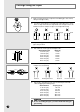
ENGLISH Drain Pump Installation (optional) Accessories 1 Drain pump & Float switch M4x12 Tapped screw Cable-tie Cable clamp 1 4 2 2 Connect the cable to the electrical component box as shown at the figure. ◆ Connect the drain pump cable to yellow terminal(CN74) and the float switch to black terminal(CN51). Note Drain pump 2 Float switch Screw the drain pump to the side of the indoor unit with two screws.
Troubleshooting Detection of errors ◆ If an error occurs during the operation, an LED flickers and the operation is stopped except the LED. ◆ If you re-operate the air conditioner, it operates normally at first, then detect an error again.
ENGLISH LED Display Indicators Concealed Type Abnormal conditions Blue Operating Red Standard Type Self-diagnostic error (including the indoor unit not detected) Displayed on appropriate indoor unit which is operating Displayed on outdoor unit 1. Error of electronic expansion valve close 2. Error of electronic expansion valve open X X 3. Breakaway of EVA OUT sensor 4. Breakaway of EVA IN sensor 5.
Troubleshooting (cont.) Wired remote controller ◆ If an error occurs, is displayed on the wired remote controller. ◆ If you would like to see an error code, press the Test button.
ENGLISH Chapter OPTIONAL ACCESSORIES ■ Parts List . . . . . . . . . . . . . . . . . . . . . . . . . . . . . . . . .
Parts List Receiver & Display Unit Accessories Concealed Type Receiver & display unit 1 STS 2S-2x10 2S-4x12 tapped screw tapped screw Wire kit (length 10m) Owner’s instructions Installation manual 4 2 1 1 1 Receiver & display unit M4x16 tapped screw Cable-tie Cable clamp Wire kit (length 10m) Owner’s instructions Installation manual 1 7 2 5 1 1 1 Owner’s instructions Installation manual 1 1 Standard Type Wireless Remote Controller Accessories E-24 Wireless remote controller
ENGLISH Wired Remote Controller Accessories Wired remote controller Cable-tie Cable clamp 1 2 2 M4x16 tapped Indoor unit power screw drawing cable Owner’s instructions Installation manual 1 7 1 1 Centralized Controller Accessories Centralized controller Cable-tie Cable clamp M4x16 tapped screw Owner’s instructions Installation manual 1 2 5 7 1 1 Function Controller Accessories Function controller Cable-tie Cable clamp M4x16 tapped screw Owner’s instructions Installation manual
THIS AIR CONDITIONER IS MANUFACTURED BY: ESTE AIRE ACONDICIONADO HA SIDO FABRICADO POR: CE CLIMATISEUR EST FABRIQUE PAR: QUESTO CONDIZIONATORE D’ARIA È PRODOTTO DA: ESTE APARELHO DE AR CONDICIONADO É FABRICADO POR: DIESE KLIMAANLAGE IST FABRIZIERT VON: AYTH H ™Y™KEYH KATA™KEYA™THKE A¶O: ùíéí äéçÑàñàéçÖê àáÉéíéÇãÖç îàêåéâ: ELECTRONICS Printed in Korea