Television Video Cassette Recorder Chassis : Model : Television Video Cassette Recorder C17A (TS-10 ) TW20P14X/BWT CONTENTS 1. Precautions 2. Specifications 3. Disassembly and Reassembly 4. Alignment and Adjustment 5. Troubleshooting 6. Exploded View and Parts List 7. Electrical Parts List 8. Block Diagram 9. Wiring Diagram 10.
ELECTRONICS © Samsung Electronics Co., Ltd. Feb.
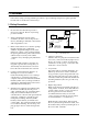
Precautions 1. Precautions Follow these safety, servicing and ESD precautions to prevent damage and protect against potential hazards such as electrical shock and X-rays. 1-1 Safety Precautions 1. Be sure that all of the built-in protective devices are replaced. Restore any missing protective shields. 2. When reinstalling the chassis and its assemblies, be sure to restore all protective devices, including: nonmetallic control knobs and compartment covers. 3.
Precautions 1-1 Safety Precautions (Continued) 9. High voltage is maintained within specified limits by close-tolerance, safety-related components and adjustments. If the high voltage exceeds the specified limits, check each of the special components. 10. Design Alteration Warning: Never alter or add to the mechanical or electrical design of this unit. Example: Do not add auxiliary audio or video connectors. Such alterations might create a safety hazard.
Precautions 1-2 Servicing Precautions Warning1: First read the “Safety Precautions” section of this manual. If some unforeseen circumstance creates a conflict between the servicing and safety precautions, always follow the safety precautions. Warning2: An electrolytic capacitor installed with the wrong polarity might explode. 1. Servicing precautions are printed on the cabinet. Follow them. 2.
Precautions 1-3 Precautions for Electrostatically Sensitive Devices (ESDs) 1. Some semiconductor (“solid state”) devices are easily damaged by static electricity. Such components are called Electrostatically Sensitive Devices (ESDs); examples include integrated circuits and some field-effect transistors. The following techniques will reduce the occurrence of component damage caused by static electricity. 2.
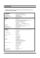
2. Specifications The descriptions and characteristics given in this booklet are given for information purposes only and are subject to modification without notice.
MEMO 2-2 Samsung Electronics
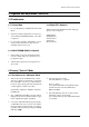
Alignment and Adjustments (Electrical) 4. Alignment and Adjustments (Electrical) 4-1 Preadjustment 4-1-1 Factory Mode 4-1-3 When CRT Is Replaced 1. Do not attempt these adjustments in the Video Mode. Make the following adjustments after setting up purity and convergence: 2. The Factory Mode adjustments are necessary when either the EEPROM (IC902) or the CRT is replaced. White Balance Sub-Brightness Vertical Center Vertical Size Horizontal Size 3.
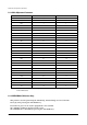
Alignment and Adjustments (Electrical) 4-2-2 Main Adjustment Parameters OSD ABBREVIATION RANGE INITIAL DATA AGC 63 28 XP 7 5 QSS 1 1 SBT 23 6 SCT 23 10 SCR 13 6 STT 13 9 RG 63 38 GG 63 32 BG 63 32 TCT 1 0 SC 63 11 SL 63 30 VA 63 38 PVS 63 27 PHS 63 40 NVS 63 38 NHS 63 22 CDL 15 4 SCL 3 1 PWL 15 12 OMD 63 26 BLR 63 31 BLB 63 27 AGC2T 31 15 PF 3 2 RP 3 2 YD 15 5 NOTE : PVS, PVA, PHS, NVS, NVA,NHS parameters must be aligned
Alignment and Adjustments (Electrical) 4-2-4 Option BYTE ITEM 0 1 LANGUAGE EUROPE/URSSIA 2 SYSTEM CF/CI/CW/CX/CB/CII 3 TUNER 1/2 4 HELP MESSAGE ON/OFF 5 VCR HEAD 2HD/2HDLP/4HD/HIFI 6 G-CODE SHOWVIEW/VIDEO PLUS/NONE 7 ATS OPTION ON/OFF 8 VPS/PDC PDC/VPS/NONE 9 TTX ON/OFF BYTE ITEM 0 1 Contrast 2 Bright 3 Sharpness 4 Color 5 Tint 6 Volume 7 Program Number 8 Color System 9 Sound System 4-3 Reset 3DB LNA Panel Lock Language Clock Timer On Time Sleep PICTURE M
Alignment and Adjustments (Electrical) 4-4 Other Adjustments 4-4-1 General 1. Usually, a color TV needs only slight touch-up adjustment upon installation. Check the basic characteristics such as height, horizontal and vertical sync and focus. 2. The picture should have good black and white details. There should be no objectionable color shading; if color shading is present, perform the purity and convergence adjustments described below. 3. Use the specified test equipment or its equivalent. 4.
Alignment and Adjustments (Electrical) 4-4-4 FOCUS Adjustment 1. Input a black and white signal. 2. Adjust the tuning control for the clearest picture. 3. Adjust the FOCUS control for well defined scanning lines in the center area of the screen. 4-4-5 Screen Adjustment 1. Turn to the ACTIVE channel. 2. Adjust the VR screen for a normal picture is (no blooming or flyback line). 3. Adjust the FOCUS control for well defined scanning lines in the center area of the screen. 4-4-6 Purity Adjustment 1.
Alignment and Adjustments (Electrical) 4 Pole Magnet 2 Pole Magnet 6 Pole Magnet 2 POLE PURITY Clamper Screw ADJUST (VERTICA YOKE CLAMP SCREW 6 POLE CONVERGENCE 4 POLE CONVERGENCE Fig. 4 -1 Convergence Magnet Assembly Vertical Green Belt 31m/m Fig.4-2 Center Convergence Adjustment 4-4-7 White Balance Adjustment 4-4-7 (A) HIGH-LIGHT ADJUSTMENT 1. Input either a Lion Head or a “pure white” pattern. 2. Warm up the TV for 30 minutes. 3. Check the data in the Service Mode 4.
Alignment and Adjustments (Electrical) 4-4-8 Center Convergence Adjustment 1. Warm up the receiver for at least 20 minutes. 2. Adjust the two tabs of the 4 pole magnets to change the angle between them. Superimpose the red and blue vertical lines in the center area of the screen. 3. Adjust the Brightness and Contrast controls for a well defined picture. 4. Adjust the two-tab pairs of the 4 pole magnets, and change the angle between them.
Alignment and Adjustments (Electrical) 4-5 Electrical Adjustment (VCR Section) 4-5-1 Preparation Electrical adjustments are required after replacing circuit components and certain mechanical parts. It is important to perform these adjustment only after all repairs and replacements have been com pleted. Also, do not attempt these adjustments unless the proper equipment is available. White (100%) signal White (75%) signal Burst Signal (as fiat as possible) 0.7V 0.3V 0.
Alignment and Adjustments (Electrical) 4-5-3 PROGRAM SW SW POSITION a I II b III IV d c V e VI f VII SW A SW B SW C S/SEN E/SEN OFF ON OFF ON POWER OFF LOAD END STANDBY LOAD START REV PLAY SPT1 SPT2 F/R1 F/R2 FL SW : ON-less than 3.5v / OFF-more than 3.
MEMO 4-10 Samsung Electronics
Troubleshooting 5. Troubleshooting 5-1 No Power (No Picture on) Check both terminal voltages of C813 (125V) Yes No Check both terminal voltages of C805 (280~300V). Yes Is IC801S Pin 3 19~22V? Yes Check/Replace T801S No Check D801S~804S FD801S No No Check whether each power line is short or open. No Check IC801S /Zener diode Check Voltage of A5V,A3.3V, A15V power line. Yes Is IC201S Pin 54 Voltage 3.3V? Yes No Check/Replace IC901. No Check/Replace IC902. Check H.
Troubleshooting 5-2 No RF Picture / Sound Check IC201S #40, #24 No Yes Yes Check IC201S R, G, B, pins 51, 52, 53 Check Another I2C bus line No Check After bus line open No Replace IC201S Yes Check Q401, Q402 No Replace Yes Check FBT No Replace 5-2 Samsung Electronics
Troubleshooting 5-3 No Picture (Sound OK) 1 Check the Brightness, Contrast and Color adjustments 2. Check: AV Picture, Video Playback 3. See Video Block Diagram 5-4 No Sound (Picture OK) 1. Check the Volume adjustment level. 2. Check AV Video, Sound Playback 3. See Audio Block Diagram 5-5 RF Weak Signal (Playback, AV Mode OK) 1. Check Tuner (TU01S) B+. Check : 9V, 33V, 5V (CN802A) 5-6 Recording Defect 1. CN802A Check : Retouch 2. 2nd Tuner (TU02S) B+. Check : 33V(LT02) 5V (JTV501) 3.
Troubleshooting 5-7 No Color 1. Check the Color Adjustment level 2. Check the Sandcastle Pulse Line : IC201S #34 3. Check the R-Y, B-Y Line : IC201S #51~#53 5-8 No Vertical SCAN 1. Check L301, L302, C310 2. Check IC301, #2 3. Check IC201S #21, #22 4. Check DY Connector 5-9 Horizontal Size 1.
Troubleshooting 5-10 Play Mode Inoperative RF-VIDEO No See Video Missing In RF Mode No See (Regulator Inoperative) Yes Insert a Cassette Tape Recorded by Another VCR and Press Play Button Yes Play Indication in Display Yes Mechanism Operation Yes PB-Video No See (Mechanism Does Not Operate in Play Mode) Does Not Operate or Operates but Stops Soon No See Video Missing in Play Mode Yes See (PB Audio) Audio Missing in Play Mode Samsung Electronics 5-5
Troubleshooting 5-11 Mechanism Does Not Operate In Play Mode Mechanism Does Not Operate In Play Mode Place VCR Power On Load a Tape and Press Play Button Yes Tape Loading Operation (Load) ICM601-38 : HIGH ICM601-39 : LOW No No Moter B+ ICM602-3, 9, 21 No Motor B+ Line Yes or VCR Stops Soon Replace ICM601 (S.End Sensor) ICM601-77,76 Low Replace ICM602 Check Tape High Cylinder Rotation No See (Cylinder Does Not Rotate) No Check CYL FG.
Troubleshooting 5-12 Record Mode Inoperative No Play Operation See (Play Mode Inoperative) Yes Load VCR With a Blank Tape and Press Record Button Yes Tape Eject No Rec SW Logic ICM601 No Change Tape Replace Yes Replace SWM611 D/ REC (H) ICM601-66 Low Check ICM601 High REC-Video No See (Video Missing in Record Mode) Yes See (Audio Mising in Record Mode) Samsung Electronics 5-7
Troubleshooting 5-13 Fast Forward Mode Inoperative Load VCR With a Tape and Press F.Fwd Button Yes Mechanism State ICM601-63, 64,65 (STOP) See (Mechanism Does Not Operate In Play Mode) (STOP) See (Capstan Does Not Rotate) (F.
Troubleshooting 5-14 Rewind Mode Inoperative Load VCR With a Tape No See (Fast Forward Mode Inoperative) (STOP) See (Mechanism Does Not Operate In Play Mode) (Rotate) Press Rewind Button Yes Mechanism State ICM601-63, 64,65 (Rew) Capstan Motor Rotation (STOP) See ICM601-25 (Rotate) Check Mechanism Samsung Electronics 5-9
Troubleshooting 5-15 Rev Search Mode Inoperative See Play Mode Inoperative No Play Operation Yes Press REV Search Button Yes Play Speed Capstan Speed Check Mechanism Replace ICM601 Serach Speed Noise Bar Locking Yes Replace ICM601 5-10 No Rec SW Logic ICM601 No Change Tape Replace Yes Capstan Motor Samsung Electronics
Troubleshooting 5-16 Cassette Loading Mechanism Does Not Operate Turn the VCR Power On and Insert a Tape Tape Loading Yes Press Eject Button No Check ICM601 Samsung Electronics No Check (Control Pulse) ICM601-76,77 No Check Start/End Sensor ICM601 No Check LM B+ Line No Replace ICM602 Yes ICM601 - 39 Yes ICM602-12:LOW ICM602-11:HIGH 5-11
Troubleshooting 5-17 No Servo Lock Play C-FG ICM601-93 No Check Start/End Sensor ICM601 No Check A/C Head Yes CTL Pluse ICM601-4 Yes Check CTL Pulse AC Level (SP, LP : Over 2Vp-p) No Yes Replace ICM601 5-12 Samsung Electronics
Troubleshooting 5-18 Capstan Does Not Rotate 9V CNM603-5 No Check 12V at AL15V Line of Power Supply No Check A5V at AL6V Line of Power Supply No Check I-LIMIT. RM618 No Check C.M CTL/ RM606, RM604 Yes AL 5V CNM603-8 Yes Place the VCR In Play Mode Yes CNM603-3 2.5V Yes 2.
Troubleshooting 5-19 Drum Does Not Rotate Check 12V ICM602-9,21 No Check 12V Yes Place the VCR In Play Mode Yes CYL-Speed Faster Check D-FG,D-PG ICM601-96,97Square Wave No Replace XTM601, CM609, CM610 Slower (8 MHz) XTM601 Yes Check Cylinder Motor 5-14 Samsung Electronics
Troubleshooting 5-20 Video Missing In Play Mode No Video EE Mode Operation See (Video Missing In EE Mode) Yes Place VCR Play Mode Yes Video FM In ICM301-17 No Check ICM301-18 No Check Video Head Yes Video ICM301-20 No Check QM302 Yes Video ICM301-29 No Check Video Out Line Yes Replace ICM301 Samsung Electronics 5-15
Troubleshooting 5-21 Video Missing In Record Mode Video EE Mode Operation No TV Switching Circuit Check Yes Place VCR Record Mode Yes FM-Video ICM301-21 No Replace ICM301 Yes FM-Video ICM301-18 No Check RM313 Yes Check Video Head 5-16 Samsung Electronics
Troubleshooting 5-22 Color Missing In Play Mode FM-ENV ICM301-61 No See (Video Missing In Play Mode) No S/W 25Hz ICM301-11 Yes Color ICM301-71 No Check ICM601 Yes Yes Check XTM301 : 4.
Troubleshooting 5-23 Color Missing In Record Mode (VIdeo In) Record Mode No TV Switching Circuit Check No Check XTM301 : 4.
Troubleshooting 5-24 Audio Signal Missing in Play Mode (MONO MODE) Check ICM301 pin75 : 5V No Check PC 5V Line No Check VCR MICOM (ICM601- pin27, 28) No Check A/C Head and PB EQ Block (AUDIO HEAD AZIMUTH) Yes Check ICM301 pin23,24 (IC CLK DATA) Yes Check ICM301 pin 1 : PB Audio Signal (Small Signal) Yes Check ICM301 pin100 : PB audio signal (Small Signal) No Check CM301 Yes Check ICM301 pin96 : PB Audio Signal No Replace ICM301 Yes Check TV NICAM PART(Sound Block) Samsung Electronics 5-19
Troubleshooting 5-25 Audio Signal Missing After Recording (MONO MODE) Check IC702 #14 MONO out No Check IC702 Yes Place VCR in REC Mode Yes Check ICM301 pin 75: 5V No Check PC 5V Line Yes Check ICM301 pin7 REC audio signal No Replace ICM301 Yes Check FLM501 Pin5 REC bias signal No Check CM370, RM357, RM358 CM371, CM373, CM372, QM312, RM359 No Check A/C Head Assembly Yes Check CNM302 , Pin5 Yes Replace CNM302 5-20 Samsung Electronics
Electrical Parts List You can search for the updated part code through ITSELF web site. URL : http://itself.sec.samsung.co.kr 7. Electrical Parts List 7-1 TW20P14X/BWT Loc. No. Code No.
Electrical Parts List Loc. No.
Electrical Parts List Loc. No.
Electrical Parts List Loc. No.
Electrical Parts List Loc. No.
Electrical Parts List Loc. No. 5 5 5 5 5 6 6 6 7 6 3 3 2 3 3 3 3 3 3 3 3 3 3 3 3 3 3 3 3 3 3 3 3 3 3 3 3 3 3 3 3 3 3 4 4 4 4 3 4 4 4 4 3 4 4 4 4 3 4 4 4 4 3 4 4 4 3 4 4 4 4 4 4 4 4 4 4 7-6 J202 HIC01 GT01 GT02 A ICM301 PCB ICM601 C612 C607 Q401 PC801S PT801S NT801S CY801S CR402S CR410S CX801S C805 RL801S CN502A CN801B CN802B PCB+SC T801S T444S T401 LR401S L402 LX801S GT101A D810 Q803 IC301 IC801S Q813 D822 D823 D825 D827 D811 D812 D816 D820 D806 D828 Code No.
Electrical Parts List Loc. No. 4 4 4 4 4 4 4 4 4 4 4 4 4 4 4 4 4 4 4 4 4 4 4 4 4 4 4 4 4 4 4 4 4 4 4 4 4 4 4 4 4 4 4 4 4 4 4 4 4 4 4 4 4 4 4 4 4 4 4 4 4 4 4 4 4 4 4 4 4 4 4 4 4 4 4 4 4 Code No.
Electrical Parts List Loc. No. 4 4 4 4 4 4 2 3 3 3 3 3 3 3 3 4 4 4 3 4 4 4 4 4 4 4 4 4 4 4 4 4 4 4 4 4 4 4 4 4 2 3 3 3 3 3 4 4 4 4 4 4 4 4 4 2 3 3 2 3 3 3 2 2 3 3 3 3 2 3 3 3 3 3 3 3 2 7-8 GT302 GT401 GT402 GT801 GT802 V999S CN502B CN501B IC501 IC501 SCR501 H/S501 D502 D503 D504 D501 DZ501 R507 R508 R509 R506 R501H R502H R503 C503 C501 C502 C506 C504 JC500 JC501 PCB GT502 SW811S CN801 PCB EY801 EY802 EY803 EY804 EY805 EY806 GTM801 GTM802 DE+FD PW+FD FD+BF Code No.
Electrical Parts List Loc. No. 2 2 2 2 2 2 2 Code No. AA59-00221E 4301-000121 HA69-00276A AA68-02264A HA68-00816B AA68-01120A 6801-001073 Description ; Specification Remark Loc. No. Code No. Description ; Specification Remark REMOCON ,TM66,SAA5554PS,38,G6671B,S/S, BATTERY-MN 1.5V,-,AAA,10.5x44.5m,HOLDER BAG VINYL HDPE,T0.
Electrical Parts List MEMO 7-10 Samsung Electronics
Block Diagrams 8. Block Diagrams 8-1 Notes The TVCR’s 1st and 2nd tuners are “multi-system.” compatible: IC201S (TDA9361/9381) is the video, chroma, and deflection (UOC) IC . 8-1-1 TAPE PLAYBACK (REGARDLESS OF ORIGINAL RECORDING SYSTEM) If the output PB signal of micom pin 12 is high, the PB signal outputs from ICM301 pin 29, passes through IC 702 pins 2 and 3 and out to another VCR . The output signal of IC701 pin 1 (pin 15) outputs from IC201S pin 42 .
Block Diagrams 8-2 C17A PCB Layout 8-2 Samsung Electronics
Wiring Diagram 9.
Schematic Diagrams 10.
Schematic Diagrams 10-2 MAIN2 ( VOC & TUNER BOX) 10-2 Samsung Electronics
Schematic Diagrams 10-3 MAIN3 ( VCR A/V BLOCK ) TP01 TP02 TP09 TP03 TP10 TP11 TP04 TP05 TP08 TP07 Samsung Electronics 10-3
Schematic Diagrams 10-4 MAIN4 ( SWITCHING BLOCK) 10-4 Samsung Electronics
Schematic Diagrams 10-5 MAIN5( OPTION-PAL HIFI BLOCK ) Samsung Electronics 10-5
Schematic Diagrams 10-6 MAIN6 ( OPTION-VCR SECAM BLOCK ) 10-6 Samsung Electronics
Schematic Diagrams 10-7 POWER & FBT Samsung Electronics 10-7
Schematic Diagrams 10-8 CRT 10-8 Samsung Electronics
Schematic Diagrams 10-9 FRONT A/V, MASTER SW FRONT A/V Samsung Electronics MASTER SW 10-9