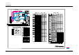
PCB Layout 9. PCB Layout 9-1 PCB-MAIN Loc. No.
Schematic Diagrams 11.
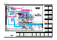
Schematic Diagrams 11-2 MAIN 2/4 TP13 IC201 30PIN TP14 IC201 32PIN TP15 IC201 37PIN TP16 IC201 41PIN TP17 IC201 43PIN TP18 IC201 45PIN TP18 TP16 TP21 TP14 TP20 TP13 TP19 TP15 TP17 TP19 IC201 47PIN TP2 TP12 TP5 TP6 TP10 TP4 TP1 IC201 2 PIN TP2 IC201 4 PIN TP3 IC201 7PIN TP21 IC201 53PIN TP10 IC201 25PIN TP11 IC201 27PIN TP8 IC201 23PIN TP9 IC201 24PIN TP9 TP8 TP3 TP12 IC201 28PIN TP11 TP1 TP7 TP20 IC201 49PIN TP4 IC201 19PIN TP5 IC201 20PIN TP6 IC201 21PIN TP7 IC201 22PIN
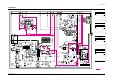
Schematic Diagrams 11-3 MAIN 3/4 TP24 TP24 TP25 IC801 1 PIN TP26 TP25 TP27 TP27 T444 10 PIN TP26 : Power Line Si l Li Samsung Electronics 11-3
Schematic Diagrams 11-4 MAIN 4/4 : Power Line : Signal Line 11-4 Samsung Electronics
COLOR TELEVISION RECEIVER Chassis : Model: COLOR TELEVISION RECEIVER K15A CT331HBZX CT331EBZX CT331HBX CT331HX CT3366BZX CT3338ZX CT501EBZX CT501HX CT5066BZX CT5038ZX CONTENTS 1. Precautions 2. Specifications 3. Disassembly and Reassembly 4. Alignment and Adjustments 5. Troubleshooting 6. Exploded Views and Parts List 7. Electric Parts List 8. Block Diagram 9. PCB Layout 10. Wiring Diagrams 11.
ELECTRONICS © Samsung Electronics Co., Ltd. JUN.
Precautions 1. Precautions Follow these safety, servicing and ESD precautions to prevent damage and protect against potential hazards such as electrical shock and X-rays. 1-1 Safety Precautions 1. Be sure that all of the built-in protective devices are replaced. Restore any missing protective shields. 2. When reinstalling the chassis and its assemblies, be sure to restore all protective devices, including: nonmetallic control knobs and compartment covers. 3.
Precautions 1-1 Safety Precautions (Continued) 9. High voltage is maintained within specified limits by close-tolerance, safety-related components and adjustments. If the high voltage exceeds the specified limits, check each of the special components. 10. Design Alteration Warning: Never alter or add to the mechanical or electrical design of this unit. Example: Do not add auxiliary audio or video connectors. Such alterations might create a safety hazard.
Precautions 1-2 Servicing Precautions Warning1: First read the “Safety Precautions” section of this manual. If some unforeseen circumstance creates a conflict between the servicing and safety precautions, always follow the safety precautions. Warning2: An electrolytic capacitor installed with the wrong polarity might explode. 1. Servicing precautions are printed on the cabinet. Follow them. 2.
Precautions 1-3 Precautions for Electrostatically Sensitive Devices (ESDs) 1. Some semiconductor (Òsolid stateÓ) devices are easily damaged by static electricity. Such components are called Electrostatically Sensitive Devices (ESDs); examples include integrated circuits and some field-effect transistors. The following techniques will reduce the occurrence of component damage caused by static electricity. 2.
Specifications 2.
Disassembly and Reassembly 3. Disassembly and Reassembly 3-1 Back Cover Removeal Fig. 3-1 1. After removing the screws, pull the cabinet backwards.
Disassembly and Reassembly 3-2 Main Board Removal Fig. 3-2 Fig. 3-3 1. Separate the socket board from the CRT neck. 2. Remove the Anode Cap from the CRT. 3. Remove the main board by pulling it with both hands. Warning: The FBT is charged with high voltage. Before removing the Anode Cap, discharge the voltage through one of the heat sinks on the main board.
Disassembly and Reassembly 3-3 Speaker Removal 1. Loosen the screws and remove the speakers. Fig.
Disassembly and Reassembly 3-4 CRT Removel Fig. 3-5 1. Spread a soft mat on the floor. Place the TV set face down. 2. Remove the 4 nuts mounting the CRT to the front cabinet. 3. Lift the CRT. 4. Caution: Because of the high vacuum and large surface area of the picture tube, be careful while handling it: (1) Always lift the picture tube by grasping it firmly around the faceplate, (2) Never lift the tube by its neck. (3) Do not scratch the picture tube or apply excessive pressure.
Alignment and Adjustments 4. Alignment and Adjustments 4-1 Service Mode Adjustments 4-1-1 Service Mode Menus Since there are no VRs in the K15A chassis, all adjustments after parts replacement must be done in the Service Mode. Service Mode adjustments are necessary when either the EEPROM (IC902) or the CRT is replaced.
Alignment and Adjustments 4-1-3 Adjustment in Option Mode 4-1-4 Service Mode Adjustments This adjustment is necessary whenever the EEPROM is replaced. Input data (as marked on the back cabinet). ADJUSTMENT PATTERN OPTION RESET Select “SET OPTION” by pressing the Channel ▼ key twice. ADJUSTMENT PATTERN OPTION RESET Press MENU to go back to the factory mode. ADJUSTMENT PATTERN OPTION RESET Press volume + key. POWER OFF 2. Refer to 4-2 for other adjustments.
Alignment and Adjustments 4-2 Alignment and Adjustment 4-2-1 General Alignment Instructions 1. Usually, a color TV needs only slight touch-up adjustment upon installation. Check the basic characteristics such as picture height, focus and a horizontal and vertical sync. 2. Observe the picture and check for good back and white details. There should be no objectionable color shading: If color shading is present, demagnetize the receiver.
Alignment and Adjustments 4-2-8 Sub-Contrast Adjustment 4-2-10 Sub-Color Adjustment 1. Input a gray scale pattern. Use a pattern generator (PM5518). 1. Do sub-color adjustment after the SubContrast and Sub-Tint adjustments. 2. Short D208 to switch off the ABL feed-back. 2. D208 should still be shorted. The ABL should still be switched OFF. 3. Check CN201 R-OUT with an oscilloscope. 4. Set RC, BC, GC data to 0 in the Service Mode. 5. Adjust SCT to 2.40 ± 0.1Vp-p 3. Input a color bar pattern.
Alignment and Adjustments 4-2-11 White Balance Adjustment 4-2-13 Vertical Size Adjustment 1. Input a lion head pattern. 4-2-11 (A) LOW-LIGHT ADJUSTMENTS 1. Input either a lion head or “pure white” color pattern. 2. After the vertical center adjustment, enter into the service mode. 3. Adjust VA so that the each top and bottom of the screen is 4.0. If the top and bottom values are different, adjust VA so that the sum of the two values is 8.0. 2. Operate the receiver for 30 minutes. 3.
Troubleshooting 5. Troubleshooting 5-1 No Power No Power OFF Check LED when AC code is plugged. ON Check IC802. Abnormal Abnormal Normal Check Fuse. Check/Replace IC802, R812, D856. Check IC801* Pin 1 Oscillation. Check and Replace D807 ~D810 Abnormal Abnormal (0 ~ 15V) Check/Replace D806, Q401, Q801, D802, D814* Abnormal (0V) Check/Replace PC802, DZ807 Samsung Electronics Check IC801 Pin 3 B+. Normal (15~20V) Check IC801* Pin 4 Voltage Normal (0.
Troubleshooting 5-2 No Sound No Sound Normal Abnormal Normal Check Waveform of IC201 Pin 52. Check Waveform of IC601 Pin 1. Abnormal Check Connector CN601 and CN701. Normal Abnormal Check CN601 and CN701 Connector Soldering and A/V PCB. Check Waveform of IC601 and IC602 Pins 4. Normal Ok Abnormal Check Waveform of IC201 Pin 1. Normal Check Voltage of IC601 and IC602 Pin 5. Abnormal Volume Up. O.K Check SIF (L201). Normal (approx. 12V) Abnormal Check Power 12V Line Voltage.
Troubleshooting 5-3 Horizontal Line Appears Single Horizontal Line Normal (24V) Abnormal Check Waveform of IC201 Pins 22,24. Check 24V-C Voltage. Abnormal Check FBT Pin 2 (24V) Oscillation. NG Normal Check Whether O.K a horizontal line appears in Normal the service mode.. Samsung Electronics Check/Replace FBT. Open NG Check/Replace IC201. Check R409 Open. Check/Replace IC301. Check/Replace R409.
Troubleshooting 5-4 No Signal No Signal Abnormal Check each tuner terminal voltage. Check voltage line. Normal Check tuner SCL,SDA waveform. Abnormal Normal Check Micom IC901. Check IC201 Pins 7,8 waveform. Check whether AGC and AFTadjustment are normal in the service mode. Normal (2Vp-p) Check IC201 Pin 43 waveform level. Abnormal Check IC201 Pins 19,20, 21 waveform level. 5-4 Replace tuner. Abnormal Check IC201 Pin 47 waveform level. Readjust AGC and AFT.
Exploded Views & Parts List 6.
Exploded Views & Parts List 6-2 CT501E No 1 1-1 Description Specification Q’ty Remark AA64-30978X AA63-50305A AA63-50310A AA64-70010D AA64-10635A AA61-60003J AA65-30105A AA95-90030M AA60-10002A AA61-40053A 3001-001034 6002-000514 AA64-40408A AA64-40407A AA64-10637A CABINET-FRONT GRILLE-WOOFER,R GRILLE-WOOFER,L BADGE-BRAND KNOB-POWER,T SPRING-CS CLAMP-WIRE ASSY-PCB,A/V FRONT SCREW-TAPPING STOPPER-PCB SPEAKER SCREW-TAPPING INDICATOR-LED WINDOW-REMOCON KNOB-CONTROL ,CT501EBZ,BK708P EGB,HIPS,HB, -,501E
Exploded Views & Parts List 6-3 CT331H No Code No Description 1-1 1-2 1-3 1-4 1-5 1-6 1-7 1-8 1-9 1-10 1-11 1-12 AA64-31232B AA64-31232E AA64-70009G AA64-40495A AA64-10768B AA61-60003T AA65-30105A AA61-40113A AA61-40010A 3001-000003 6002-000514 AA64-10767A 6002-000514 AA64-40496A CABINET-FRONT CABINET-FRONT BADGE-BRAND WINDOW-REM KNOB-POWER;SPRING-CS;-,SU CLAMP-WIRE STOPPER-PCB BOSS-WING SPEAKER SCREW-TAPPING KNOB-CONTROL SCREW-TAPPING INDICATOR-LED ;-,CT-331HB,BK708P HITRON,HIPS, ;-,CT-331HBZ,BK708
Exploded Views & Parts List 6-4 CT501H No 1 6-4 Code No Description Specification Q’ty 1-1 1-2 1-3 1-4 1-5 1-6 1-7 1-8 1-9 1-10 1-11 AA64-31232B AA64-31232E AA64-70009G AA64-40495A AA64-10768B AA61-60003T AA65-30105A AA61-40113A 3001-000003 6002-000514 AA64-10767A 6002-000514 AA64-40496A CABINET-FRONT CABINET-FRONT BADGE-BRAND WINDOW-REMOCON KNOB-POWER SPRING-CS CLAMP-WIRE STOPPER-PCB SPEAKER SCREW-TAPPING KNOB-CONTROL SCREW-TAPPING INDICATOR-LED -,CT-331HB,BK708P HITRON,HIPS, -,CT-331HBZ,BK708P
Exploded Views & Parts List 6-5 CT3366 No Code No Description Specification Q’ty 1 1-1 1-2 1-3 1-4 1-5 1-6 1-7 1-8 1-9 1-10 1-11 1-12 1-13 1-14 AA64-30850F AA63-50274A AA63-30120N AA64-70009G AA64-40360A AA64-10582E AA61-60003T AA64-40184A AA95-90030M 3722-000506 AA60-10002A AA61-40010A AA91-60301A 6002-000522 AA64-10559B CABINET-FRONT GRILLE-WOOFER COVER-CONTROL,A BADGE-BRAND WINDOW-REMOCON KNOB-POWER SPRING-C INDICATOR-LED ASSY-PCB,A/V FRONT JACK-RCA SCREW-TAPPING BOSS-WING ASSY-HOLDER,SPK SCREW-
Exploded Views & Parts List 6-6 CT5066 6-6 No Code No Description Specification Q’ty 1 1-1 1-2 1-3 1-4 1-5 1-6 1-7 1-8 1-9 1-10 1-11 1-12 1-13 1-14 1-15 AA64-30678K AA63-50196A AA64-60284F AA63-30072Z AA64-70010D AA64-40360A AA64-10560E AA61-60003T AA64-40184A 3722-000506 AA95-90032S AA60-10002A AA61-40015A AA91-60302A 6002-000522 AA64-10559B CABINET-FRONT GRILLE-WOOFER INLAY-AV COVER-CONTROL,A BADGE-BRAND WINDOW-REMOCON KNOB-POWER SPRING-CS INDICATOR-LED JACK-RCA ASSY-PCB,A/V FRONT SCREW-TAPPING
Exploded Views & Parts List 6-7 CT3338 3-1 3 3-2 2-2 2-1 2 1-9 1-8 3-3 1-7 1-6 1-1 1-2 1-3 1-4 1-5 No Code No Description Specification Q’ty 1 1-1 1-2 1-3 1-4 1-5 1-6 1-7 1-8 1-9 AA64-30151W AA64-60161Q AA64-70009G AA64-40057A AA64-10153B AA61-60003J AA64-40189A AA64-10052A 3001-000281 AA61-40010A CABINET-FRONT INLAY-AV BADGE-BRAND WINDOW-REMOCON KNOB-POWER,T SPRING-CS INDICATOR-LED KNOB-CONTROL SPEAKER BOSS-WING -,CT3338Z,PA100 HITRON EG, V-MODEL,NTSC TVI EG,PS,T0.
Exploded Views & Parts List 6-8 CT5038 No 6-8 Code No Description Specification Q’ty 1 1-1 1-2 1-3 1-4 1-5 1-6 1-7 1-8 1-9 1-10 1-11 1-12 1-13 1-14 AA64-31263B AA64-60161Q AA64-70015B AA64-40085A AA64-10187B AA61-60003J AA63-50056A AA61-40007A AA95-90030M AA60-10002A AA64-40188A AA64-10050A 3001-000191 6002-000514 AA61-40010A CABINET-FRONT INLAY-AV BADGE-BRAND WINDOW-REMOCON KNOB-POWER,T SPRING-CS GRILLE-WOOFER STOPPER-PCB ASSY-PCB,A/V FRONT SCREW-TAPPING INDICATOR-LED KNOB-CONTROL SPEAKER SCREW-T
Electric Parts List 7. Electric Parts List 7-1 Part Differences (by screen size) ....................................................................................... 7-1 7-2 CT331EBZX/STR (CT331EBZX/GSU AND CT331EBZX/STR Dissimilar Parts)............ 7-9 7-3 CT331HX/SPL (CT331EBZX/GSU AND CT331HX/SPL Dissimilar Parts) ..................... 7-9 7-4 CT331HBX/DIS (CT331EBZX/GSU AND CT331HBX/DIS Dissimilar Parts) ................
No. 1 2 3 4 5 6 7 8 Electric Parts List 7-2 7-1 Part Differences (by screen size) U.S.A LATIN INC H SPECIFICATION CODE No. 14" A34KQV42X,+380mG,14" AA03-10001D 20" A48KRD82X(H),+380mG,21" AA03-10029W 14" DSE-1422FL,14" AA27-50001K ← 20" DSE -1992LL1(H),20" AA27-50004W ← 14" 22.5MM AA27-60001E ← 20" -,JH-291-(JH-8210) AA27-60001D ← 14" 7P,22.5PI,12PI,S N 3704-001089 ← 20" 9P,15.24PI,26.
Samsung Electronics 7-1-1 Inch Option No. 1 2 3 4 5 6 7 8 9 10 12 U.S.A LATIN INC H SPECIFICATION CODE No. 14" C-C 722 1.6KV 2306-000253 ← ← HORIZONTAL CT CAPACITOR 20" C-C 742 1.
13 14 15 16 17 18 19 20 21 22 Samsung Electronics 23 24 Loc. No. U.S.A LATIN INC H SPECIFICATION CODE No. 14" C-E 0.47uF 50V 2401-001333 ← 20" C-E 0.47uF 50V 2401-001333 ← 14" R-C 56K-J 1/8T 2001-000864 ← 20" R-C 62K-J 1/8T 2004-001990 ← 14" R-M.O 2W 3.3-J 2003-001036 ← 20" R-M.O 1W 1.5-J 2003-000436 ← 14" 8P 300MM AA39-20109D ← 20" 8P 400MM AA39-20109A ← 14" R-C 33K-J 1/8T 2001-000660 ← 20" R-M 7.
Samsung Electronics No. 25 26 27 28 29 30 31 32 33 34 35 37 U.S.A LATIN INC H SPECIFICATION CODE No. SPECIFICATION 14" C-C 20pF(CH) 2201-000354 ← 20" C-C 20pF(CH) 2201-000354 X 14" R-C 820-J 1/8T 2004-000995 ← 20" R-C 1.2K-J 1/8T 2001-000221 ← 14" R-C 820-J 1/8T 2004-000995 ← 20" R-C 1.2K-J 1/8T 2001-000221 ← 14" R-C 820-J 1/8T 2004-000995 ← 20" R-C 1.
AC 110V ONLY No. FREE VOLT REMARK Loc. No. SPECIFICATION CODE No. SPECIFICATION CODE No.
Samsung Electronics 7-1-4 X-Ray Option X-RAY USED No. X-RAY DELETE REMARK Loc. No. SPECIFICATION CODE No. SPECIFICATION CODE No. 1 CX01 C-C 103 25V 2202-000127 X X X-RAY 2 CX02 10uF 50V 2401-000480 X X X-RAY 3 CX03 10uF 50V 2401-000480 X X X-RAY 4 CX04 471 500V 2201-000556 X X X-RAY 5 DX01 MTZ6.
~73, ~38, ~1F SYSTEM (1 SPK1 / 1 AMP) No. ~1H SYSTEM (2 SPKs / 1 AMP) ~39,~85,~66,~1E,~3E SYSTEM ( 2 SPKs / 2 AMPs) Loc. No. REMARK SPECIFICATION CODE No. SPECIFICATION CODE No. SPECIFICATION CODE No. 1 IC602 X X X X ASSY-H/S LA4425 AA96-50392A WHEN USING 2 AMPs 2 C652 X X X X 2.
Electric Parts List 7-2 CT331EBZX/STR (CT331EBZX/GSU AND CT331EBZX/STR Dissimilar Parts) Loc. No. Code No. Description ; Specification Remark Loc. No. Code No.
Electric Parts List 7-4 CT331HBX/DIS (CT331EBZX/GSU AND CT331HBX/DIS Dissimilar Parts) Loc. No. Code No. Description ; Specification Remark Loc. No. Code No. ASSY-PCB,MAIN 0402-000534 DIODE-RECTIFIER;RG10V,400V,1.2A,DO-201,TP 2001-000449 R-CARBON;2.2Kohm,5%,1/8W,AA,TP,1.8x3.2m 2401-001998 C-AL;1000uF,20%,25V,GP,TP,10x20,5mm 3812-000219 WIRE-NO SHEATH CU;TCWA,300V,52mm(TAPING),1/0.6mm AA68-50067ALABEL-RATING;T/P 90(G),T0.
Electric Parts List 7-6 CT501EBZX/GSU (CT331EBZX/GSU AND CT501EBZX/GSU Dissimilar Parts) Loc. No. Code No. Description ; Specification Remark Loc. No. Code No. ASSY-PCB,MAIN ! ! ! ! ! Description ; Specification Remark ASSY-CRT * AA94-10140AASSY-PCB,MAIN(OPT);CT501EBZX/GSU,K15A,BOLIVIA,- C301 C302 C305 C402 C403 C404 CN501 CN802 R204 R205 R206 R214 R226 R303 R304 R305 R306 R307 R308 R309 R404 R411 R412 R518 RH01 RH02 T444 V999 2301-000223 C-FILM,PEF;22nF,5%,100V,TP,7.2x4.5x9.
Electric Parts List Loc. No. Code No. Description ; Specification Remark Loc. No. Code No. ASSY-CABINET,FRONT Description ; Specification Remark ASSY-ACCESSORY * AA91-10297V ASSY-CABINET,FRONT;-,CT501EBZ,BK708P EGB,HB,BLK KNOPOW AA61-60003J SPRING-CS;-,SUS304,0.5,OD6,H12,N7,-,-,AA63-50305AGRILLE-WOOFER,R;-,501E,PA110 3R,SECC,T0.5,-,AA63-50310AGRILLE-WOOFER,L;-,501E,PA110 3R,SECC,T0.
Electric Parts List 7-9 CT501HX/SPL (CT331EBZX/GSU AND CT501HX/SPL Dissimilar Parts) Loc. No. Code No. Description ; Specification Remark Loc. No. ASSY-PCB,MAIN ! ! ! ! ! * AA94-10134V ASSY-PCB,MAIN(OPT);CT501HX/SPL,KCT15A,JUNGNAMMI C301 C302 C305 C402 C403 C404 C409 C808 C810 C910 CLAMP/F CLAMP/W CN501 CN802 D814 IC901 R204 R205 R206 R214 R226 R303 R304 R305 R306 R307 R308 R309 R404 R411 R412 R518 R604 R908 R934 R936 RH01 RH02 T444 V999 2301-000223 C-FILM,PEF;22nF,5%,100V,TP,7.2x4.5x9.
Electric Parts List 7-10 CT331EBZX/GSU Loc. No. Code No.
Electric Parts List Loc. No. ! ! ! ! ! ! ! C914A C915 CN501 CN601 CN701 CN802 CU02 D101 D102 D201 D202 D203 D204 D205 D206 D207 D208 D210 D299 D301 D302 D401 D402 D403 D404 D405 D407 D601 D701 D704 D802 D803 D805 D806 D807 D808 D809 D810 D814 D855 D856 D902 D903 D904 D905 D906 DZ801 DZ802 DZ803 DZ806 DZ807 DZ901 DZ902 DZ903 EL301~802 EY401~830 F801 F801A F801B GT101~806 GT101A IC201 IC301 IC601 IC602 Code No.
Electric Parts List Loc. No. R202 R203 R204 R205 R206 R207 R208 R209 R210 R211 R212 R213 R214 R215 R218 R219 R222 R223 R226 R227 R228 R229 R230 R231 R233 R234 R235 R236 R237 R239 R240 R241 R242 R251 R252 R253 R257 R301 R302 R303 R304 R305 R306 R307 R308 R309 R401 R402 R403 R404 R405 R406 R407 R408 R409 R410 R411 R412 R413 R415 R416 R417 R444 R501 R502 7-16 Code No.
Electric Parts List Loc. No. ! ! ! ! R923 R924 R925 R926 R927 R928 R929 R930 R931 R932 R933 R934 R936 R937 R940 R951 R952 R998 RM01 RM02 RM901 RU02 RU06 RU07 RU10 SF101 SW901 SW902 SW903 SW904 SW905 SW906 T401 T444 T801 TU01 V999 WIRE1 WIRE2 X201 X202 X901 Z201 Z601 Code No. Description ; Specification Remark 2001-000281 R-CARBON;100ohm,5%,1/8W,AA,TP,1.8x3.2mm 2001-000449 R-CARBON;2.2Kohm,5%,1/8W,AA,TP,1.8x3.2m 2001-000449 R-CARBON;2.2Kohm,5%,1/8W,AA,TP,1.8x3.
Electric Parts List 7-11 CT5066BZX/STR (CT3366BZX/XAP AND CT5066BZX/STR Dissimilar Parts) Loc. No. Code No. Description ; Specification Remark Loc. No. ASSY-PCB,MAIN * * Code No. Description ; Specification Remark AA90-70100P ASSY-CABINET;5066,CT5066BZX/STR AA94-10140HASSY-PCB,MAIN(OPT);CT5066BZX/STR,K15A,PERU,AA64-30680B CABINET-BACK;-,5066,-,HIPS,HB,BLK,-,AA65-30107ACLAMP-D,COIL;NYLON 66,V2,NTR,-,20~22 INCH,- C301 2301-000223 C-FILM,PEF;22nF,5%,100V,TP,7.2x4.5x9.
Electric Parts List 7-12 CT5066BZX/XAP (CT3366BZX/XAP AND CT5066BZX/XAP Dissimilar Parts) Loc. No. Code No. Description ; Specification Remark Loc. No. Code No. ASSY-PCB,MAIN Description ; Specification Remark ASSY-CABINET * AA94-10140J ASSY-PCB,MAIN(OPT);CT5066BZX/XAP,K15A,PANAMA,- C301 2301-000223 C-FILM,PEF;22nF,5%,100V,TP,7.2x4.5x9.
Electric Parts List 7-14 CT3366BZX/XAP Loc. No. Code No.
Electric Parts List Loc. No. ! ! ! ! ! ! ! ! CN501 CN601 CN701 CN802 CU02 D101 D102 D103 D201 D202 D203 D204 D205 D206 D207 D208 D210 D299 D301 D302 D401 D402 D403 D404 D405 D407 D601 D701 D704 D802 D803 D805 D806 D807 D808 D809 D810 D814 D855 D856 D902 D903 D904 D905 D906 DZ801 DZ802 DZ803 DZ806 DZ807 DZ901 DZ902 DZ903 EL301~802 EY401~803 F801 F801A F801B GT101~806 GT101A IC201 IC301 IC601 IC602 IC801 Code No.
Electric Parts List Loc. No. R202 R203 R204 R205 R206 R207 R208 R209 R210 R211 R212 R213 R214 R215 R218 R219 R222 R223 R226 R227 R228 R229 R230 R231 R233 R234 R235 R236 R237 R239 R240 R241 R242 R251 R252 R253 R257 R301 R302 R303 R304 R305 R306 R307 R308 R309 R401 R402 R403 R404 R405 R406 R407 R408 R409 R410 R411 R412 R413 R415 R416 R417 R444 R501 R502 7-22 Code No.
Electric Parts List Loc. No. ! ! ! ! R922 R923 R924 R925 R926 R927 R928 R929 R930 R931 R932 R933 R934 R936 R937 R940 R951 R952 R988 RM01 RM02 RM901 RU02 RU06 RU07 RU10 SF101 SW901 SW902 SW903 SW904 SW905 SW906 T401 T444 T801 TU01 V999 WIRE1 WIRE2 X201 X202 X901 Z201 Z601 Code No. Description ; Specification Remark 2001-000281 R-CARBON;100ohm,5%,1/8W,AA,TP,1.8x3.2mm 2001-000281 R-CARBON;100ohm,5%,1/8W,AA,TP,1.8x3.2mm 2001-000449 R-CARBON;2.2Kohm,5%,1/8W,AA,TP,1.8x3.2m 2001-000449 R-CARBON;2.
Electric Parts List 7-15 CT5038ZX/GSU (CT3338ZX/XAP AND CT5038ZX/GSU Dissimilar Parts) Loc. No. Code No. Description ; Specification Remark Loc. No. ASSY-PCB,MAIN * AA94-10140DASSY-PCB,MAIN(OPT);CT5038ZX/GSU,K15A,BOLIVIA,- C301 2301-000223 C-FILM,PEF;22nF,5%,100V,TP,7.2x4.5x9.0mm, C302 2201-000556 C-CERAMIC,DISC;470pF,10%,500V,Y5P,TP,7x4,5 C305 2305-000149 C-FILM,MPEF;100nF,5%,100V,TP,12x12.5x6.5,5 C402 2306-000355 C-FILM,MPPF;7.4nF,5%,1.6KV,TP,28.5x18.
Electric Parts List 7-16 CT5038ZX/XAP (CT3338ZX/XAP AND CT5038ZX/XAP Dissimilar Parts) Loc. No. Code No. Description ; Specification Remark Loc. No. ASSY-PCB,MAIN Code No. Description ; Specification Remark ASSY-CRT * AA94-10140E ASSY-PCB,MAIN(OPT);CT5038ZX/XAP,K15A,PANAMA,- C301 2301-000223 C-FILM,PEF;22nF,5%,100V,TP,7.2x4.5x9.
Electric Parts List 7-17 CT3338ZX/XAP Loc. No. Code No.
Electric Parts List Loc. No. CN701 ! CN802 ! ! ! ! ! ! ! CU02 D101 D102 D103 D201 D202 D203 D204 D205 D206 D207 D208 D210 D299 D301 D302 D401 D402 D403 D404 D405 D407 D601 D701 D704 D802 D803 D805 D806 D807 D808 D809 D810 D814 D855 D856 D902 D903 D904 D905 D906 DZ801 DZ802 DZ803 DZ806 DZ807 DZ901 DZ902 DZ903 EL301~802 EY401~830 F801 F801A F801B GT101~806 GT101A IC201 IC301 IC601 IC801 IC802 IC901 IC902 Code No. Description ; Specification Remark 3711-002646 CONNECTOR-HEADER;BOX,7P,1R,2.
Electric Parts List Loc. No. R205 R206 R207 R208 R209 R210 R211 R212 R213 R214 R215 R218 R219 R222 R223 R226 R227 R228 R229 R230 R231 R233 R234 R235 R236 R237 R239 R240 R241 R242 R251 R252 R253 R257 R301 R302 R303 R304 R305 R306 R307 R308 R309 R401 R402 R403 R404 R405 R406 R407 R408 R409 R410 R411 R412 R413 R415 R416 R417 R444 R501 R502 R503 R504 R505 7-28 Code No.
Electric Parts List Loc. No. ! ! ! ! R925 R926 R927 R928 R929 R930 R931 R932 R933 R934 R936 R937 R940 R951 R952 R988 RM01 RM02 RM901 RU02 RU06 RU07 RU10 SF101 SW901 SW902 SW903 SW904 SW905 SW906 T401 T444 T801 TU01 V999 WIRE1 WIRE2 X201 X202 X901 Z201 Z601 Code No. Description ; Specification Remark 2001-000449 R-CARBON;2.2Kohm,5%,1/8W,AA,TP,1.8x3.2m 2001-000008 R-CARBON;15Kohm,5%,1/8W,AA,TP,1.8x3.2mm 2001-000290 R-CARBON;10Kohm,5%,1/8W,AA,TP,1.8x3.2mm 2001-000864 R-CARBON;56Kohm,5%,1/8W,AA,TP,1.8x3.
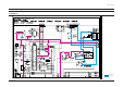
Block Diagram 8. Block Diagram IC601 TU01* TUNER TELH9-212A SOUND-AMP 2.5W x 1CH LA4425 SAW M1859M DUAL IC201 IC902 1CHIP IF/V/C/D KA2163B EEPROM KS24C020 R.G.B CRT I2C BUS Q401* IC901* H-TR KSC5368 MICOM SZM-354ET EXT IN EXT IN VIDEO AUDIO T444* VERTICAL-AMP KA2131 D807 ~ D810 IC801* SPS CONTROL KA3SO680 KA3S0765 Samsung Electronics F.B.T 14" : FSV14A001 20" : FSV20A001 21" : FSV20A001 T801* SWITCHING TRANS (125V) S:125V,12.5V (12.