PORTABLE DVD PLAYER DVD-L200W DVD-L200 SERVICE MANUAL DVD-L200W/DVD-L200 ELECTRONICS SERVICE Manual PORTABLE DVD PLAYER CONTENTS 1. Precautions 2. Troubleshooting 3. Exploded Views and Parts List 4. Electrical Parts List 5. Block Diagram 6. Schematic Diagrams This Service Manual is a property of Samsung Electronics Co .,Ltd. Any unauthorized use of Manual can be punished under applicable International and/or domestic law. © Samsung Electronics Co., Ltd. SEP.
1. Precautions 1-1 Safety Precautions 1) Before returning an instrument to the customer, always make a safety check of the entire instrument, including, but not limited to, the following items: (1) Be sure that no built-in protective devices are defective or have been defeated during servicing. (1)Protective shields are provided to protect both the technician and the customer. Correctly replace all missing protective shields, including any removed for servicing convenience.
Precautions 2) Read and comply with all caution and safety related notes on or inside the cabinet, or on the chassis. 3) Design Alteration Warning-Do not alter or add to the mechanical or electrical design of this instrument. Design alterations and additions, including but not limited to, circuit modifications and the addition of items such as auxiliary audio output connections, might alter the safety characteristics of this instrument and create a hazard to the user.
Precautions 1-2 Servicing Precautions CAUTION : Before servicing units covered by this service manual and its supplements, read and follow the Safety Precautions section of this manual. Note : If unforseen circumstances create conflict between the following servicing precautions and any of the safety precautions, always follow the safety precautions. Remember: Safety First. 1-2-1 General Servicing Precautions (1) a.
Precautions 1-3 ESD Precautions Electrostatically Sensitive Devices (ESD) Some semiconductor (solid state) devices can be damaged easily by static electricity. Such components commonly are called Electrostatically Sensitive Devices(ESD). Examples of typical ESD devices are integrated circuits and some field-effect transistors and semiconductor chip components. The following techniques should be used to help reduce the incidence of component damage caused by static electricity.
Precautions 1-4 Handling the optical pick-up The laser diode in the optical pick up may suffer electrostatic breakdown because of potential static electricity from clothing and your body. WRIST-STRAP FOR GROUNDING 1M The following method is recommended. (1) Place a conductive sheet on the work bench (The black sheet used for wrapping repair parts.) (2) Place the set on the conductive sheet so that the chassis is grounded to the sheet.
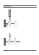
Precautions 1-5 Pick-up disassembly and reassembly 1-5-1 Disassembly 1-5-2 Assembly 1) Remove the power cord. 2) Disassemble the Ass’y-DVD Deck. 3) Make solder land 3 points short on Pick-up FPC. (See Fig. 1-4) 4) Disassemble the Pick-up. 1) Replace the Pick-up. 2) Remove the soldering 3 points on Pick-up FPC. 3) Reassemble the Ass’y-DVD Deck. Note : If the assembly and disassembly are not done in correct sequence, the Pick-up may be damaged.
Samsung Electronics A No focus incoming and no disc occurs. Yes LD is outputted from object lens at play key input? No Disc recognition No B Check Deck Ass'y. Yes FE in SIC1-8 is within specified range? A No focus incoming No Check RIC1 and A, B, C, D input. 2.
2-2 Check the Deck Ass'y and connection Yes SIC1-13output is normal? No pick-up home positing No Check SIC1 Yes RIC1-22 is 5V? LD out pick-up replace. Yes Current exceeds 0.1A? Yes Divide RQ1 emitter terminal voltage and 5V real voltage difference into 6.2ohm. B NO LD CD ON No No Open check in related circuit.
Samsung Electronics See "Fine Seek Check" Yes TE occurs in search range? Yes Actual velocity occurs at SIC1-13 terminal? Yes TEZISLV, SIC1-6 output is normal? No Search Operation No No No Focus On? Check SIC1 peripheral circuit. Check RIC1 peripheral circuit. Yes RFAGCO, RIC1-71 output level is normal? No A Check pick-up. No No No No No Yes Check Deck Ass'y. Yes SIC1-3 output is normal? No Check RIC1-31 terminal. Time out due to many jump counts. Check SIC1 Peripheral curcuit.
2-4 No Yes RIC1-71 output are normal? Yes RIC1-1 output is normal? No Check RIC1 peripheral circuit and A, B, C, D. No Check RIC1 soldering and power. Check Deck ass'y and connection Check path to RIC1 and SIC1. After resoldering SIC1. No No Check or replace disc motor or check SIC1, MIC1. Yes SIC3-7 output (FG) is normal? Yes SPD output is normal? (SIC1-28) Yes Input of RF signal is normal? (SIC1-152) Abnormal rotation of disc motor Check Jack3 peripheral soldering shot.
Samsung Electronics Check Jack1, Jack2 peripheral soldering shot. Yes AIC06, AIC07-1,5 output is normal? Yes Jack1, Jack2 output is normal? Headphone output error No No Check AIC02, AIC03-4 output. Check Jack1, Jack2 output error. Check Jack3 peripheral soldering shot. Yes Output in Jack3 is normal? Yes Output in ZIC1-181 is normal? Digital output error No No Check Jack3. Check ZIC01 peripheral circuit.
2-6 Check AIC01 peripheral circuit. Yes AIC185-1,7 output is normal? Yes AIC02 output is normal? Yes AIC05-5, 8, 14, 18 output is normal? Speater output error No No No Check AIC185 peripheral circuit. Check AIC02 peripheral circuit. Check AIC05 peripheral circuit. Check the cable.
Samsung Electronics Check the cable. Yes Video signal of about 1V appears at output jack at pin3? Yes Peak to peak voltage level of VR104? Yes Power is normal at pin 1, 16 in VIC01. Yes Analog signals are inputted normally at pin4 in VIC01? Yes Analog output is normal at pin 169 in ZIC1? Yes 27MHz clock input is normal at pin 161 in ZIC1? Yes No No No No No No Check the connection between VIC01 and output jack. Check the soldering of VIC01.
2-8 No No No No No No No No Check the connection to posotive pin in PE118. Check the connection betwen pin93 in XIC01 and pin5 in XIC06. Check the soldering of XIC01. About 27MHz clock input is normal at pin2 in XIC01. Check the connection between pin4,5 in XCON1 and pin4 in XQ102. Check the connection between base in XQ101 and pin62 in UIC01. Check the connection between pin44 in ZIC1 and pin38 in XCON1. Check the connection between pin36 in XCON15 and PF501.
3. Exploded View and Parts List Page 3-1 Cabinet Assembly - - - - - - - - - - - - - - - - - - - - - - - - - - - - - - - - - - - - - - - - - 3-2 3-2 Deck Assembly - - - - - - - - - - - - - - - - - - - - - - - - - - - - - - - - - - - - - - - - - - - 3-4 Notice You can search for the updated part code through ITSELF web site. URL; http://itself.sec.samsung.co.
3-2 6 0 e q 8 H100 8 8 9 0 ‘ 8 8 r (MAIN B PCB) 7 ) ‘ 7 + R (MAIN A PCB) E ( 1 t (TERMINAL PCB) 8 * & ‘ @ “ 2 3 + U 4 w Q % ‘ ‘ T (KEY PCB) 5 = y # ‘ Y “ $ “ # ^ UT01 ! ‘ ‘ ‘ Exploded Views and Parts List 3-1 Cabinet Assembly
Exploded Views and Parts List Loc. No 1 2 3 4 5 6 7 8 9 10 11 12 13 14 15 16 17 18 19 20 21 22 23 24 25 26 28 29 30 31 32 33 34 35 36 37 H100 UT01 Parts No.
Exploded Views and Parts List 3-2 Deck Assembly H115 H101 H103 H104 H112 S.N.A.
Exploded Views and Parts List Loc. No H101 H102 H103 H104 H105 H106 H107 H108 H109 H110 H111 H112 H113 H114 H115 H116 H117 Parts No. AK63-00023A AK61-00080A AK61-00081A AK73-00010A AK97-00319A AK61-00076A AK97-00320A AK66-00020A AK97-00312A AK31-00007A AK61-00074A AK61-00079A AK61-00082A AK61-00078A 6001-001197 6001-001288 6002-001119 Description ; Specification Remark COVER-PU;DP-P2,SUS 304 T=0.
Exploded Views and Parts List MEMO 3-6
4. Electrical Parts List Loc.
Electrical Parts List Loc.
Electrical Parts List Loc.
Electrical Parts List Loc.
Electrical Parts List Loc.
Electrical Parts List Loc.
Electrical Parts List Loc.
Electrical Parts List Loc.No Part No Description ; Specification VR102 VR103 VR104 VR105 VR106 VR107 VR108 VR110 VR111 VR112 VR113 VR114 VR115 VR196 VR197 2007-001164 2007-000094 2007-001164 2007-000075 2007-000084 2007-000084 2007-000121 2007-001164 2007-001164 2007-001164 2007-001164 2007-001164 2007-001164 2007-000097 2007-000078 R-CHIP;75ohm,1%,1/10W,TP,1608 R-CHIP;22Kohm,5%,1/10W,TP,1608 R-CHIP;75ohm,1%,1/10W,TP,1608 R-CHIP;220ohm,5%,1/10W,TP,1608 R-CHIP;4.7Kohm,5%,1/10W,TP,1608 R-CHIP;4.
Electrical Parts List Loc.No Part No Description ; Specification BR132 BR135 BR165 BR199 BR201 BT101 PAL 2007-000086 2007-000079 2007-000090 2007-000090 2007-000033 2601-001104 2007-000070 R-CHIP;5.6Kohm,5%,1/10W,TP,1608 R-CHIP;1.8Kohm,5%,1/10W,TP,1608 R-CHIP;10Kohm,5%,1/10W,TP,1608 R-CHIP;10Kohm,5%,1/10W,TP,1608 R-CHIP;0ohm,5%,1/4W,TP,3216 TRANS-SMD,PULSE;6:900MH,0.
Electrical Parts List MEMO 4-10 This Document can not be used without Samsung’s authorization Samsung Electronics
5.
Block Diagram MEMO 5-2 This Document can not be used without Samsung’s authorization Samsung Electronics
6.
Schematic Diagrams 6-1 DCDC/Battery (Main B PCB) 6-2 This Document can not be used without Samsung’s authorization Samsung Electronics
Schematic Diagrams 6-2 Power (Main A PCB) Samsung Electronics This Document can not be used without Samsung’s authorization 6-3
Schematic Diagrams 6-3 AV-Decoder (Main A PCB) 6-4 This Document can not be used without Samsung’s authorization Samsung Electronics
Schematic Diagrams 6-4 Servo (Main A PCB) Samsung Electronics This Document can not be used without Samsung’s authorization 6-5
Schematic Diagrams 6-5 Video 1/Audio 2 (Main B PCB) 6-6 This Document can not be used without Samsung’s authorization Samsung Electronics
Schematic Diagrams 6-6 Video 2 (Main A PCB) Samsung Electronics This Document can not be used without Samsung’s authorization 6-7
Schematic Diagrams 6-7 Audio 1 (Main A PCB) 6-8 This Document can not be used without Samsung’s authorization Samsung Electronics
Schematic Diagrams 6-8 Display (Main A PCB) Samsung Electronics This Document can not be used without Samsung’s authorization 6-9
Schematic Diagrams 6-9 Key/Sub-Micom 6-10 This Document can not be used without Samsung’s authorization Samsung Electronics
Schematic Diagrams 6-10 LCD Samsung Electronics This Document can not be used without Samsung’s authorization 6-11
Schematic Diagrams 6-11 Inverter 6-12 This Document can not be used without Samsung’s authorization Samsung Electronics