iDCS 500 TECHNICAL MANUAL INSTALLATION TABLE OF CONTENTS NOVEMBER 2001 T A B L E O F C O N T E N T S I N S TA L L AT I O N S E C T I O N PART DESCRIPTION PAGE 1 SITE REQUIREMENTS............................................................................1.1 2 INSTALLING SINGLE CABINET AND MULTIPLE CABINET CONFIGURATIONS 3 2.1 UNPACKING AND INSPECTION ................................................ 2.1 2.2 SINGLE CABINET INSTALLATION–WALL OR FLOOR MOUNT . 2.1 2.
iDCS 500 TECHNICAL MANUAL 4 5 INSTALLATION TABLE OF CONTENTS NOVEMBER 2001 3.13 TRUNK B CARD ........................................................................ 3.10 3.14 TRUNK B1 CARD ...................................................................... 3.10 3.15 TRUNK C1 CARD ...................................................................... 3.10 3.16 GTRK CARD.............................................................................. 3.10 3.17 DID CARD ..........................
iDCS 500 TECHNICAL MANUAL 6 7 8 INSTALLATION TABLE OF CONTENTS NOVEMBER 2001 5.7 T1 CIRCUIT ................................................................................. 5.2 5.8 BRI CIRCUIT ............................................................................... 5.2 CONNECTING STATION EQUIPMENT 6.1 SAFETY PRECAUTIONS ............................................................. 6.1 6.2 KEYSETS .................................................................................... 6.1 6.
iDCS 500 TECHNICAL MANUAL 9 10 11 INSTALLATION TABLE OF CONTENTS NOVEMBER 2001 8.3 iDCS KDB-FULL DUPLEX (FKDBF) ............................................ 8.1 8.4 KDB-DLI ...................................................................................... 8.1 8.5 KDB-SLI ...................................................................................... 8.2 8.6 CONNECTING TO THE KDBS .................................................... 8.2 SOFTWARE AND DATABASE MANAGEMENT................
iDCS 500 TECHNICAL MANUAL INSTALLATION PART 1 NOVEMBER 2001 PART 1. SITE REQUIREMENTS When you are planning the installation of the iDCS 500 system, choose a site that meets the following requirements: • • • • • • • • • • Select a location for the iDCS 500 system that has enough space for easy installation and adequate lighting (see Figure 1–1). Select a location that will minimize cable lengths. See the Cable Requirements Table in the iDCS 500 General Description Section.
iDCS 500 TECHNICAL MANUAL INSTALLATION PART 1 NOVEMBER 2001 11.81" 22.32" 19.76" 59.28" 39.
iDCS 500 TECHNICAL MANUAL INSTALLATION PART 2 NOVEMBER 2001 PART 2. INSTALLING SINGLE CABINET AND MULTIPLE CABINET CONFIGURATIONS 2.1 UNPACKING AND INSPECTION The iDCS 500 can be configured as a single cabinet, a dual cabinet system or a three cabinet system. A iDCS 500 single cabinet system may be wall, floor, or rack mounted while multiple cabinets systems may only be floor or rack mounted. Do not attempt to wall mount any system other than a single cabinet system.
iDCS 500 TECHNICAL MANUAL INSTALLATION PART 2 NOVEMBER 2001 (minimum size #10) screws (see Figure 2–1). Hang the iDCS 500 cabinet onto the screws installed in the backboard. A separate single point ground must be connected to the cabinet ground bar prior to installing any cards. (Refer to Part 2.6 Grounding). When a Power supply is installed, verify that the power switch is in the proper voltage setting, i.e., 110 position (see Figure 2–6). NOTE: Wall mount a single cabinet configuration only.
iDCS 500 TECHNICAL MANUAL INSTALLATION PART 2 NOVEMBER 2001 2. Place the upper cabinet on top of the main/lower cabinet ensuring that the upper cabinet locating bumps are snug in the lower cabinet locating dimples. Install the two provided screws in the dimples in the front lower panel of the upper cabinet and the two provided screws in the dimples in the rear lower panel of the upper cabinet. Replace the rear panel on the upper cabinet.
iDCS 500 TECHNICAL MANUAL INSTALLATION PART 2 NOVEMBER 2001 provided screws in the dimples in the rear lower panel of the top cabinet. Replace the rear panel on the top cabinet. A separate single point ground must be connected to the main cabinet ground bar. Install the ground harness between the cabinets ground bars prior to installing any cards (refer to Part 2.6 Grounding). When a power supply is installed, verify that the power switch is in the proper voltage setting, i.e.
iDCS 500 TECHNICAL MANUAL INSTALLATION PART 2 NOVEMBER 2001 4. Install the cabinets in the rack, leaving approximately 2 inches of space between each cabinet to allow cable access, and secure each cabinet with eight screws in the mounting flange holes (see Figure 2–9). NOTE: The 2 inch gap between cabinets requires a longer Cabinet Interconnect Cable (CICR) than usual for multiple cabinet installations. 5. Reattach the ground bar to each cabinet and connect them together as described in Part 2.
iDCS 500 TECHNICAL MANUAL INSTALLATION PART 2 NOVEMBER 2001 The supplementary equipment grounding conductor shall not be smaller in size than the ungrounded branch-circuit supply conductors. The supplementary equipment grounding conductor shall be connected to the product at the terminal provided, and shall be connected to ground in a manner that will retain the ground connection when the product is unplugged from the receptacle.
iDCS 500 TECHNICAL MANUAL INSTALLATION PART 2 NOVEMBER 2001 for safety reasons to protect personnel working on the iDCS 500 system and also for operational reasons to accommodate ground return and/or ground-referenced analog telephone circuits, which require this solid earth ground connection for normal functioning. 2.8 POWER CONNECTIONS AC POWER CORD ASSEMBLY The AC Power Cord Assembly plugs into the AC power socket which is located on the left side of the cabinet.
iDCS 500 TECHNICAL MANUAL INSTALLATION PART 2 NOVEMBER 2001 The -48VDC cable assembly has a male 3 pin mate and lock connector on the system end (see Figure 2–7). Insert this end of the DC cable into the battery (BATT) connector on the left hand side of the cabinet. Attach the other end of the DC power cable to the – 48VDC power source. WARNING: Be sure the proper polarity is observed. Equipment damage will result if polarity is reversed.
iDCS 500 TECHNICAL MANUAL INSTALLATION PART 2 NOVEMBER 2001 Two #10 screws in 5/8" plywood backboard.
iDCS 500 TECHNICAL MANUAL INSTALLATION PART 2 NOVEMBER 2001 MOUNTING SCREWS FRONT BOTTOM LEFT SIDE ATTACHING LEGS TO MAIN CABINET FIGURE 2–2
iDCS 500 TECHNICAL MANUAL INSTALLATION PART 2 NOVEMBER 2001 MAIN CABINET CONFIGURATION (LEFT SIDE VIEW) FG GROUND BAR EARTH GROUND MAIN AND EXPANSION DUAL CABINET CONFIGURATION (LEFT SIDE VIEW) CONNECT GROUND HERE FG CONNECT EARTH GROUND HERE SYSTEM GROUNDING FIGURE 2–3
iDCS 500 TECHNICAL MANUAL INSTALLATION PART 2 NOVEMBER 2001 Power Input Location iDCS 500 POWER INPUT LOCATION FIGURE 2–4
iDCS 500 TECHNICAL MANUAL SIO2 SIO3 SIO4 LAN SLOT6 SLOT7 SLOT8 SLOT9/SCP MCP/LCP SLOT3 SLOT4 SLOT5 SLOT6 SLOT7 SLOT8 SLOT2 SLOT3 SLOT4 SLOT5 SLOT6 SLOT7 SLOT8 SLOT9/SCP MCP/LCP MCP SLOT2 C1 - S9 SLOT1 C1 - S8 C1 - S7 SLOT5 C1 - S6 SLOT4 C1 - S5 SLOT3 C1 - S4 SLOT2 C3 - S4 C3 - S5 C3 - S6 C3 - S7 PSU-B/PSU60 SLOT1 SLOT2 SLOT3 SLOT4 SLOT5 SLOT6 SLOT7 SLOT8 SLOT1 SLOT2 SLOT3 SLOT4 SLOT5 SLOT6 SLOT7 SLOT8 SLOT9/SCP MCP/LCP SLOT8 SLOT9/SCP MCP/LCP LCP SLOT
INSTALLATION PART 2 NOVEMBER 2001 FUSES 110 VOLTAGE SETTING iDCS 500 TECHNICAL MANUAL SETTING VOLTAGE ON PSU-60 AND PSU-60B FIGURE 2–6
iDCS 500 TECHNICAL MANUAL INSTALLATION PART 2 NOVEMBER 2001 WHITE (+) BLACK ( – ) CONNECT TO EITHER A OR B + – + – 12V + – 6V + + 6V 12V – – + + – – + 6V 6V – + 12V – + 12V – + – 6V + 6V – OPTION A – + 6V – + 6V OPTION B BATTERIES SHOULD BE PLACED WITHIN THREE FEET OF KSU BATTERY CABLE ASSEMBLY FIGURE 2–7
iDCS 500 TECHNICAL MANUAL INSTALLATION PART 2 NOVEMBER 2001 Bracket Screws Bracket Ground Bar Bracket Screws Bracket SIDE COVER MOUNTING BRACKETS FIGURE 2–8
iDCS 500 TECHNICAL MANUAL INSTALLATION PART 2 NOVEMBER 2001 Mounting Screw Holes Mounting Screw Holes SECURING CABINET IN A RACK FIGURE 2–9
iDCS 500 TECHNICAL MANUAL INSTALLATION PART 3 NOVEMBER 2001 PART 3. INSTALLING PRINTED CIRCUIT CARDS Before installing each card, unpack it and check it for signs of physical damage. If you detect any, do not attempt to install. Call Samsung Technical Support immediately. 3.1 MCP (see Figure 3–2) The iDCS 500 Main Control Processor (MCP) controls the system operation. The MCP installs in the MCP/LCP slot in the first cabinet of the system. The MCP is required for all system configurations.
iDCS 500 TECHNICAL MANUAL INSTALLATION PART 3 NOVEMBER 2001 LED INDICATIONS FOR L VERSION SYSTEM • MP OFF indicates the MCP card is powered down ON indicates the MCP card is booting Flicker Indicates normal operation. • SM OFF indicates the Smartmedia card is not installed or not recognized ON indicates the Smartmedia card is inserted and recognized Flicker indicates the Smartmedia card is being accessed.
iDCS 500 TECHNICAL MANUAL INSTALLATION PART 3 NOVEMBER 2001 There are several daughter boards that can mount on the MCP (see Figure 3−2). The daughter boards have offset pin connectors which prohibits improper installation of the Daughter board(s).
iDCS 500 TECHNICAL MANUAL INSTALLATION PART 3 NOVEMBER 2001 DIP SWITCH USE on the iDCS 500 MCP ON (left) OFF (right) COUNTRY SELECT COUNTRY SELECT COUNTRY SELECT COUNTRY SELECT COUNTRY SELECT 4 DIGIT STATION NUMBERS 4 DIGIT STATION GROUPS 4 DIGIT TRUNK NUMBERS ! SW 1 SW2 SW3 SW4 SW5 SW6 SW7 SW8 COUNTRY SELECT COUNTRY SELECT COUNTRY SELECT COUNTRY SELECT COUNTRY SELECT 3 DIGIT STATION NUMBERS 3 DIGIT STATION GROUPS 3 DIGIT TRUNK NUMBERS Switches 1 through 4 select the country the system is installed i
iDCS 500 TECHNICAL MANUAL INSTALLATION PART 3 NOVEMBER 2001 for the first iDCS 500 cabinet and communicates via a high speed data link to the MCP. The SCP installs in the ninth (9) slot in the first cabinet. The SCP can have three daughter boards installed as indicated by the table below.
iDCS 500 TECHNICAL MANUAL INSTALLATION PART 3 NOVEMBER 2001 3.3 LCP CARD (see Figure 3–4) The iDCS 500 Local Control Processor (LCP) is used when the system is expanded to more than one cabinet. The LCP is the processor for the second and or third iDCS 500 cabinet(s) and communicates via a high-speed data link to the MCP. The LCP installs in the MCP/LCP slot in the second or third cabinets of a multiple cabinet system. The SCP can have three daughter boards installed as indicated by the table below.
iDCS 500 TECHNICAL MANUAL INSTALLATION PART 3 NOVEMBER 2001 • LCP: LCP Processor Status OFF indicates that power is OFF ON indicates that the LCP is booting Flicker indicates normal operation. • S1~S9 Card Status OFF indicates that the card is idle or not installed ON indicates that one or more circuits on the card are in use Flicker indicates a problem with the card. 3.
iDCS 500 TECHNICAL MANUAL INSTALLATION PART 3 NOVEMBER 2001 Figure 3–7) and separate the two halves of the case. Place the LAN board face down over the three connectors, taking care to properly line them up and press gently on the back of the board to seat it. The MCP case can now be reassembled if all required daughter boards have been installed. Note: Do not forget to turn on the memory backup switch on the LAN board before installing it on the MCP (see Figures 3–6 and 3–9). 3.
iDCS 500 TECHNICAL MANUAL INSTALLATION PART 3 NOVEMBER 2001 3.9 MFM BOARD ON PROCESSOR CARD (see Figure 3-13) This board has no selectable options and installs in any available position of the MCP card when the system has one cabinet installed (see Figure 3–2). If the system has more than one cabinet the MFM board must be installed in position MCP-D3 of the MCP card, any available position of the SCP card (see Figure 3–3) or any available position of the LCP cards.
iDCS 500 TECHNICAL MANUAL INSTALLATION PART 3 NOVEMBER 2001 3.12 IOM BOARD (see Figure 3-17) This board has no selectable options and installs on the system main cabinet (see Figure 3–18). Line the IOM board up with the card slot and slide it in. Press gently on the center of the IOM board front panel to seat it and secure the board with the two screws. 3.13 TRUNK B CARD (see Figure 3–19) This card has no selectable options.
iDCS 500 TECHNICAL MANUAL INSTALLATION PART 3 NOVEMBER 2001 NOTE: If a cabinet is equipped with a single power supply unit (PSU-60B), a maximum of 56 station devices may be connected to that cabinet. However, if the cabinet is equipped with two power supply units, a maximum of 120 station devices may be connected to that cabinet. See the configuration section of the General Description Section for more details. 3.20 16DLI CARD (see Figure 3–19) There are no options to select on this card.
iDCS 500 TECHNICAL MANUAL INSTALLATION PART 3 NOVEMBER 2001 This card automatically detects DTMF or dial pulse signals from the SLT. Software and hardware settings are not required. The 8SLI has no DTMF receivers; it will share the system resources. If in a medium to high concentration of 8SLI cards or traffic, a MFM daughter board or boards should be added to a processor card to relieve congestion. NOTES: 1.
iDCS 500 TECHNICAL MANUAL INSTALLATION PART 3 NOVEMBER 2001 3.25 8MWSLI CARD (see Figure 3–19) There are no options to select on this card. Insert as many 8MWSLI cards as are needed into universal slots 1 through 7 (see Figure 3–1). Push firmly in the middle of both card ejectors on each card to ensure that it is fully inserted into the back plane connector. This card automatically detects DTMF or dial pulse signals from the SLT. Software and hardware settings are not required.
iDCS 500 TECHNICAL MANUAL INSTALLATION PART 3 NOVEMBER 2001 NOTES: 1. If a cabinet is equipped with a single power supply unit (PSU-60B), a maximum of 56 station devices may be connected to that cabinet. However, if the cabinet is equipped with two power supply units, a maximum of 120 station devices may be connected to that cabinet. See the configuration section of the General Description Section for more details. 2. Do not connect devices with a total REN greater than 5.0 to this card. 3.
iDCS 500 TECHNICAL MANUAL INSTALLATION PART 3 NOVEMBER 2001 DTPRI LED DEFINITIONS LED Name Function Status Normal Status Error Status SYN Synchronization Loss. Indicates wander or loss of framing. OFF ON LOS Loss of Signal. No PCM Clocking is being received. OFF ON AIS Alarm Indicating Signal. Indicating that all one’s are being received. OFF ON L2 Layer 2 is active. PRI messaging is being received. OFF ON IPC IPC link set up. CLK Card clock status.
iDCS 500 TECHNICAL MANUAL INSTALLATION PART 3 NOVEMBER 2001 Next, position the CADENCE card in the grooves of the card guide and gently slide the card in until it makes contact with the connector. Press gently but firmly on the top and bottom of the front edge of the card until the card sits in its connector. Ensure that you have installed the correct power supply. Now go to Part 11, Cadence Setup of this manual. 3.
iDCS 500 TECHNICAL MANUAL LED Name INSTALLATION PART 3 NOVEMBER 2001 Function Status Green – OK ST Card Status AL Card Alarm Status L1 Trunk 1 Status Off: Idle L2 Trunk 2 Status Red: Trouble L3 Trunk 3 Status Green: In Use L4 Trunk 4 Status Flash Green; Dialing Off: Card Not Ready Off: OK On: Call In Progress 3.
P W R MCP LOCATION PSU-B PSU-B B A T T PSU-B/PSU60 PSU-B/PSU60 SLOT1 SLOT1 SLOT2 SLOT2 SIO1 SLOT3 SLOT3 SIO2 SLOT4 SLOT4 SIO3 SLOT5 SLOT5 SIO4 SLOT6 SLOT6 LAN SLOT7 SLOT7 SLOT8 SLOT8 SLOT9/SCP SLOT9/SCP SM S1 S3 S5 S7 S9 MCP/LCP MISC2 MISC1 Smart Media MCP LAN S2 S4 S6 S8 CHAMP P M C P MCP/LCP iDCS 500 TECHNICAL MANUAL INSTALLATION PART 3 NOVEMBER 2001 FIGURE 3–1
iDCS 500 TECHNICAL MANUAL INSTALLATION PART 3 NOVEMBER 2001 M C P SCM MFM RCM ESM SCM MFM RCM IPM LAN S5 S1 MCP-D1 OFF CHAMP SM S1 S3 S5 S7 S9 ON S4 12345678 ON MCP LAN S2 S4 S6 S8 Smart Media MCP-D2 Smart Media SCM MFM RCM MISC MISC1 MISC2 LAN MCP-D3 S2 Memory Backup Switch MCP CARD FIGURE 3–2
iDCS 500 TECHNICAL MANUAL INSTALLATION PART 3 NOVEMBER 2001 MFM RCM SCM S C P P12 TX SCP P2 SCP-D1 MISC MFM RCM SCM RX S1 MISC1 P1 MISC2 S2 S4 S6 S8 S3 S5 S7 S9 SCP-D2 MFM RCM SCM P11 S1 SIO S2 SCP CARD SCP-D3 FIGURE 3–3
iDCS 500 TECHNICAL MANUAL INSTALLATION PART 1 NOVEMBER 2001 P12 L C P MFM RCM P10 P1 LCP-D1 TX LCP MISC MFM RCM RX S1 MISC1 MISC2 S2 S4 S6 S8 S3 S5 S7 S9 LCP-D2 S1 MFM RCM S2 P9 LCP CARD LCP-D3 P11 FIGURE 3–4
INSTALLATION PART 3 NOVEMBER 2001 ESM BOARD U9 P2 U3 U8 U7 U2 P3 U5 U4 U6 U11 P1 U11 U10 iDCS 500 TECHNICAL MANUAL FIGURE 3–5
iDCS 500 TECHNICAL MANUAL INSTALLATION PART 3 NOVEMBER 2001 ESM S5 ON S4 MCP-D1 IPM LAN 12345678 S1 Memory Backup Switch OFF ON MCP-D2 LAN Memory Backup Switch OFF ON MCP-D3 OFF S2 MCP CARD ON FIGURE 3–6
iDCS 500 TECHNICAL MANUAL INSTALLATION PART 3 NOVEMBER 2001 Screw Locations PROCESSOR CARD SCREW LOCATION FIGURE 3–7
iDCS 500 TECHNICAL MANUAL INSTALLATION PART 3 NOVEMBER 2001 P1 U8 P3 U14 U4 U17 U11 U9 U3 U16 U15 U6 U10 U12 U2 U13 U1 OFF S1 ON C7 U7 P2 U5 IPM BOARD D1 D2 D3 Memory Backup Switch FIGURE 3–8
iDCS 500 TECHNICAL MANUAL INSTALLATION PART 3 NOVEMBER 2001 P1 P3 U11 U14 U15 U9 U16 U8 U13 U10 U7 Y3 LED1 U4 U12 U18 U3 Y1 U6 OFF S1 ON U5 U1 D4 P3 C45 D3 D2 Memory Backup Switch LAN BOARD FIGURE 3–9
iDCS 500 TECHNICAL MANUAL INSTALLATION PART 3 NOVEMBER 2001 P3 U4 T3 K3 K1 T4 P2 K2 U2 D3 D4 P1 U13 U1 D2 D1 T2 P4 T1 MISC BOARD FIGURE 3–10
iDCS 500 TECHNICAL MANUAL INSTALLATION PART 3 NOVEMBER 2001 Screw Locations PROCESSOR CARD SCREW LOCATION FIGURE 3–11
iDCS 500 TECHNICAL MANUAL INSTALLATION PART 3 NOVEMBER 2001 P1 U1 U5 U7 U4 U3 U2 U6 P2 SCM BOARD FIGURE 3–12
iDCS 500 TECHNICAL MANUAL INSTALLATION PART 3 NOVEMBER 2001 P1 U1 U5 U7 U4 U3 U2 U6 P2 MFM BOARD FIGURE 3–13
iDCS 500 TECHNICAL MANUAL EJECTOR TABS SCREW LOCATION INSTALLATION PART 9 NOVEMBER 2001 SCREWS FIGURE 3–14
iDCS 500 TECHNICAL MANUAL INSTALLATION PART 3 NOVEMBER 2001 P2 U4 U9 U8 U3 U2 U1 U5 P1 RCM BOARD FIGURE 3–15
iDCS 500 TECHNICAL MANUAL INSTALLATION PART 3 NOVEMBER 2001 P1 L1 U10 L2 U5 U7 U9 U8 P2 MODEM BOARD FIGURE 3–16
iDCS 500 TECHNICAL MANUAL INSTALLATION PART 3 NOVEMBER 2001 Mounting Screws P8 SIO1 Line up holes when installing modem SIO2 P7 P6 MODEM SIO3 P1 P5 SIO4 P4 LAN Mounting Screws IOM BOARD FIGURE 3–17
P W R CABINET/SLOT NUMBERS PSU-B PSU-B B A T T PSU-B/PSU60 PSU-B/PSU60 SLOT1 SLOT1 SLOT2 SLOT2 SIO1 SLOT3 SLOT3 SIO2 SLOT4 SLOT4 SIO3 SLOT5 SLOT5 SIO4 IOM BOARD SLOT6 SLOT6 LAN SLOT7 SLOT7 SLOT8 SLOT8 SLOT9/SCP SLOT9/SCP MCP/LCP MCP/LCP iDCS 500 TECHNICAL MANUAL INSTALLATION PART 3 NOVEMBER 2001 FIGURE 3–18
TRUNK B CARD TRUNK B1 CARD TRUNK C1 CARD GTRK CARD DID CARD E&M CARD DLI CARD 16DLI CARD SLI CARD 8SLI CARD 16SLI CARD BRI CARD 8MWSLI CARD 16MWSLI CARD INTERFACE CARDS INSTALLATION PART 3 NOVEMBER 2001 X X X X X X xxxxxxxxx iDCS 500 TECHNICAL MANUAL FIGURE 3–19
iDCS 500 TECHNICAL MANUAL INSTALLATION PART 3 NOVEMBER 2001 T E P R I MFM P12 SYN AIS IPC TPI LOS L2 CLK TP2 P14 P1 P15 T1 E1 P11 SIO ON 12345678 RST S2 JP1 JP2 S2 P13 TEPRI CARD FIGURE 3–20
AAUCD CARD U7 U24 U18 U12 U19 U15 U9 U13 U14 U8 U25 U11 U21 U20 P1 Y1 U31 U30 U27 U26 U37 U36 U33 U32 U40 U38 U10 CE1 U42 U41 U6 CE2 DO NOT INSERT WITH POWER ON.
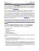
iDCS 500 TECHNICAL MANUAL INSTALLATION PART 3 NOVEMBER 2001 WITH COVER REMOVED FRONT PANEL V M 8 A xxxxxxxxx POWER REGULATOR VOICE PROCESSING MODULE SERIAL PORT PORTS 5 - 8 VOICE PROCESSING MODULE PARALLEL PORT PORTS 1 - 4 BACKPLANE CONNECTOR HDD ACCESS RUN INDICATOR DISK DRIVE RESET BUTTON *Compatible with DCS, DCS 50si, and iDCS 500.
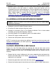
iDCS 500 TECHNICAL MANUAL INSTALLATION PART 3 NOVEMBER 2001 I T M 3 S3 S1 P2 PWR RX L2 SPD RUN TX L1 L3 P7 P6 P1 LAN P3 SIO ITM3D RST S2 ITM3D CARD FIGURE 3–23
iDCS 500 TECHNICAL MANUAL INSTALLATION PART 3 NOVEMBER 2001 E 9 1 1 ST ALM L1 L2 L3 L4 P1 P2 E911 CARD FIGURE 3–24
iDCS 500 TECHNICAL MANUAL INSTALLATION PART 4 NOVEMBER 2001 PART 4. POWER UP PROCEDURES 4.1 DETERMINING POWER SUPPLY Each cabinet on the iDCS 500 has two power supply slots the first of which must contain a PSU B and can supply up to 56 station devices or Station Equivalent Power Units (SEPU). The second PSU slot can contain either a PSUB or a PSU 60 and can supply up to 64 station devices or SEPUs.
iDCS 500 TECHNICAL MANUAL INSTALLATION PART 4 NOVEMBER 2001 4.2 CONNECT POWER TO THE SYSTEM During the initial installation, it is best to verify proper system operation before plugging in any amphenol-type cables to the MDF. If you have already plugged the cables in, unplug them. Verify that the AC voltage at the dedicated electric outlet is in the range of 88–132 VAC or 210–230 VAC. Verify that the AC voltage selection switch on the PSU is set for the proper voltage—110 or 220 VAC (see Figure 4–1).
iDCS 500 TECHNICAL MANUAL INSTALLATION PART 4 NOVEMBER 2001 unplug the system, remove the expansion cabinet power supply and check the AC fuse located on the bottom (see Figure 4–1). If the fuse is good but the LED does not illuminate, you must correct the problem before continuing. Turn off the power switch. Unplug all cards using the card ejectors. Turn the system on. Check the LEDs again. If the problem is corrected, you have a defective card. Test and remove the faulty card before continuing.
iDCS 500 TECHNICAL MANUAL INSTALLATION PART 4 NOVEMBER 2001 data assigns the 24 button keyset in the lowest port to the operator group and all trunks ring that station until the default is changed. It is recommended that the first station card be a DLI card so that the operator station will default to a keyset as extension 201. Using MMC 724, station and trunk numbers can be changed, rearranged and reassigned as needed. NOTE: Newly added station or trunk cards come up without directory numbers.
INSTALLATION PART 4 NOVEMBER 2001 FUSES 110 VOLTAGE SETTING iDCS 500 TECHNICAL MANUAL SETTING VOLTAGE ON PSU-60 FIGURE 4–1
iDCS 500 TECHNICAL MANUAL INSTALLATION PART 5 NOVEMBER 2001 PART 5. CONNECTING TELCO CIRCUITS 5.1 SAFETY PRECAUTIONS To limit the risk of personal injury, always follow these precautions before connecting TELCO circuits: a. Never install telephone wiring during a lightning storm. b. Never install telephone jacks in a wet location unless the jack is specifically designed for wet locations. c.
iDCS 500 TECHNICAL MANUAL INSTALLATION PART 5 NOVEMBER 2001 There is no special programming required for OPX use; however, it is suggested that the OPX ports are set for CO ring in MMC 208. The telephone company service facility interface code for OPX circuits is OL13C. 5.7 T1 CIRCUIT Using a standard, straight through eight conductor data cable or straight through eight conductor line cord to connect the customer provided Channel Service Unit (CSU) to the TEPRI card as shown in Figure 5–7. NOTES: 1.
iDCS 500 TECHNICAL MANUAL INSTALLATION PART 5 NOVEMBER 2001 25 PAIR CABLE WITH FEMALE CONNECTOR TO ANY TRK-B OR TRK-B1 CARD FUNCTION CIRCUIT TERM C.O. TIP COLOR PIN 1 W-BL 26 2 BL-W 1 3 W-O 27 4 O-W 2 5 W-GN 28 6 GN-W 3 7 W-BR 29 8 BR-W 4 9 W-S 30 10 S-W 5 11 R-BL 31 12 BL-R 6 1 C.O. RING C.O. TIP 2 C.O. RING C.O. TIP TELCO-PROVIDED NETWORK ACCESS JACK RJ 11C RJ 14C RJ 21X 3 C.O. RING C.O. TIP 4 C.O.
iDCS 500 TECHNICAL MANUAL INSTALLATION PART 5 NOVEMBER 2001 25 PAIR CABLE WITH FEMALE CONNECTOR TO ANY TRK-C1 CARD FUNCTION CIRCUIT TERM COLOR PIN C.O. TIP 1 W-BL 26 2 BL-W 1 3 W-O 27 4 5 O-W W-GN 2 28 6 GN-W 3 7 W-BR 29 8 9 BR-W W-S 4 30 10 S-W 5 11 R-BL 31 12 13 BL-R R-O 6 32 14 O-R 7 15 R-GR 33 16 17 GR-R R-BR 8 34 18 BR-R 9 19 R-S 35 20 S-R 10 21 BK-BL 36 22 BL-BK 11 1 C.O. RING C.O. TIP 2 C.O. RING C.O. TIP 3 C.O. RING C.O. TIP 4 C.O.
iDCS 500 TECHNICAL MANUAL INSTALLATION PART 5 NOVEMBER 2001 25 PAIR CABLE WITH FEMALE CONNECTOR TO ANY GTRK CARD FUNCTION CIRCUIT TERM COLOR PIN 1 W-BL 26 2 BL-W 1 3 W-O 27 4 O-W 2 5 W-GN 28 6 GN-W 3 7 W-BR 29 C.O. RING 8 BR-W 4 C.O. TIP 9 W-S 30 10 S-W 5 C.O. TIP 1 C.O. RING C.O. TIP 2 C.O. RING C.O. TIP 3 TELCO-PROVIDED NETWORK ACCESS JACK 4 RJ 11C RJ 14C RJ 21X C.O. RING (NO OTHER CONNECTIONS) CONNECT TO ANY CIRCUIT ON ANY GTRK CARD.
iDCS 500 TECHNICAL MANUAL INSTALLATION PART 5 NOVEMBER 2001 25 PAIR CABLE WITH FEMALE CONNECTOR TO ANY DID CARD FUNCTION COLOR PIN 1 W-BL 26 DID TIP 2 BL-W 1 DID RING 3 W-O 27 4 O-W 2 5 W-GN 28 6 GN-W 3 7 W-BR 29 DID TIP 8 BR-W 4 DID RING 9 W-S 30 10 S-W 5 DID RING CIRCUIT TERM 1 2 DID TIP DID RING TELCO-PROVIDED NETWORK ACCESS JACK RJ 11C RJ 14C RJ 21X 3 4 DID TIP (NO OTHER CONNECTIONS) CONNECT TO ANY CIRCUIT ON ANY DID CARD.
iDCS 500 TECHNICAL MANUAL INSTALLATION PART 5 NOVEMBER 2001 25 PAIR CABLE WITH FEMALE CONNECTOR TO ANY E & M CARD FUNCTION CIRCUIT TERM COLOR PIN 1 W-BL 26 2 BL-W 1 3 W-O 27 4 5 O-W W-GN 2 28 6 GN-W 3 7 W-BR 29 8 9 BR-W W-S 4 30 10 S-W 5 11 R-BL 31 12 13 BL-R R-O 6 32 14 O-R 7 15 R-GR 33 16 17 GR-R R-BR 8 34 18 BR-R 9 19 R-S 35 20 S-R 10 21 BK-BL 36 22 BL-BK 11 C.O. TIP 1 C.O. RING E1 2 M1 C.O. TIP 3 C.O. RING E2 4 M2 C.O.
iDCS 500 TECHNICAL MANUAL INSTALLATION PART 5 NOVEMBER 2001 25 PAIR CABLE WITH FEMALE CONNECTOR TO ANY SLI CARD FUNCTION CIRCUIT TERM SLT TIP COLOR PIN 1 W-BL 26 2 BL-W 1 3 W-O 27 1 SLT RING SLT TIP 2 SLT RING SLT TIP TELCO-PROVIDED NETWORK ACCESS JACK O-W 2 5 W-GN 28 6 GN-W 3 7 W-BR 29 8 BR-W 4 9 W-S 30 3 SLT RING SLT TIP RJ 11C 4 SLT RING 4 10 S-W 5 RJ 14C 11 R-BL 31 RJ 21X 12 BL-R 6 (NO OTHER CONNECTIONS) CONNECT TO ANY CIRCUIT ON ANY SLI CARD.
iDCS 500 TECHNICAL MANUAL INSTALLATION PART 5 NOVEMBER 2001 TRANSMIT PAIR 8 7 6 5 4 3 2 1 T E P R I RECEIVE PAIR CUSTOMER PROVIDED MALE RJ 45 ENDED CABLE SYN AIS IPC TPI LOS L2 CLK TP2 T1 E1 CUSTOMER-PROVIDED CUSTOMER SERVICE UNIT SIO RST TELCO T1 SPAN MDF CONNECTIONS T1/PRI CIRCUIT TO TEPRI CARD FIGURE 5–7
iDCS 500 TECHNICAL MANUAL INSTALLATION PART 5 NOVEMBER 2001 MDF CONNECTIONS TO BRI CARD PAIR FUNCTION CIRCUIT TERM COLOR PIN TX TIP TX RING 1 1 2 W-BL BL-W 26 1 RCV TIP RCV RING 1 3 4 W-0 0-W 27 2 5 6 TX TIP TX RING 2 RCV TIP RCV RING 2 28 3 7 8 W-BR BR-W 29 4 9 10 W-SL SL-W 30 5 11 12 31 6 TX TIP TX RING 3 13 14 R-O O-R 32 7 RCV TIP RCV RING 3 15 16 R-GN GN-R 33 8 17 18 TX TIP TX RING RCV TIP RCV RING 34 9 4 19 20 R-SL SL-R 35 10 4 21 22 BK-BL BL-BK 36 11 2
iDCS 500 TECHNICAL MANUAL INSTALLATION PART 5 NOVEMBER 2001 MDF STATION CONNECTIONS TO BRI CARD PAIR FUNCTION CIRCUIT TERM COLOR PIN TX TIP TX RING 1 1 2 W-BL BL-W 26 1 RCV TIP RCV RING 1 3 4 W-0 0-W 27 2 5 6 28 3 TX TIP TX RING 2 7 8 W-BR BR-W 29 4 RCV TIP RCV RING 2 9 10 W-SL SL-W 30 5 11 12 31 6 TX TIP TX RING 3 13 14 R-O O-R 32 7 RCV TIP RCV RING 3 15 16 R-GN GN-R 33 8 17 18 TX TIP TX RING RCV TIP RCV RING TWO PAIR TWISTED SHEATHED STATION CABLE 24 OR 26 AWG 34
iDCS 500 TECHNICAL MANUAL INSTALLATION PART 6 NOVEMBER 2001 PART 6. CONNECTING STATION EQUIPMENT 6.1 SAFETY PRECAUTIONS To limit the risk of personal injury, always follow these precautions before connecting telephone circuits: a. Never install telephone wiring during a lightning storm. b. Never install telephone jacks in a wet location unless the jack is specifically designed for wet locations. c.
iDCS 500 TECHNICAL MANUAL INSTALLATION PART 6 NOVEMBER 2001 6.4 SINGLE LINE TELEPHONES Using one pair twisted #24 AWG or #26 AWG jumper wire, cross-connect each single line telephone to the SLI port, 8SLI port, 8MWSLI, 16SLI or 16MWSLI port of your choice (see Figures 6–3a, 6–3b, 6-3c, 6–3d, and 6–3e) or into the KDb-SLI of your choice (see part 8 of this installation section). CAUTION: To reduce the risk of fire, use only No. 26 AWG or larger telecommunication line cord.
iDCS 500 TECHNICAL MANUAL INSTALLATION PART 6 NOVEMBER 2001 Use screw holes 4 and 5 if you are mounting on dry wall with a hole in the middle for cable access. 6.6B WALL-MOUNTING KEYSETS WITH ULTRA BASE WEDGE The keysets now come equipped with a new Ultra Base wedge. These base wedges are reversible and can be used for wall-mounting however not every wall mounting scenario is appropriate.
iDCS 500 TECHNICAL MANUAL INSTALLATION PART 6 NOVEMBER 2001 6.8 ATTACHING DCS 32 BUTTON AOM AND DCS 64B MODULES WITH MASTER STATION These new Ultra Base Wedges allow a connector clip (packaged with 64B Modules and AOMs) to be connected to the underside of the new style wedge and attach AOM(s) or 64B module(s) together with the main or “master” station. This “clip” allows multiple 64B modules and or AOMs to be secured or “chained” together to the main or “master” station they are associated with.
iDCS 500 TECHNICAL MANUAL INSTALLATION PART 6 NOVEMBER 2001 25 PAIR CABLE WITH FEMALE CONNECTOR TO ANY DLI CARD PIN COLOR TERM 26 W-BL 1 1 BL-W 2 27 W-O 3 2 O-W 4 28 W-GN 5 3 GN-W 6 29 W-BR 7 4 BR-W 30 W-S 9 5 S-W 10 31 R-BL 11 6 BL-R 12 32 R-O 13 7 O-R 14 33 R-GR 15 8 8 GR-R 16 34 R-BR 17 9 BR-R 18 35 R-S 19 10 S-R 20 36 BK-BL 21 11 BL-BK 22 CIRCUIT 1 FUNCTION DLI TIP DLI RING 2 DLI TIP DLI RING ONE PAIR TWISTED SHEATHED STATION CABL
iDCS 500 TECHNICAL MANUAL INSTALLATION PART 6 NOVEMBER 2001 25 PAIR CABLE WITH FEMALE CONNECTOR TO ANY 16DLI CARD PIN COLOR TERM CIRCUIT FUNCTION 26 1 W-BL BL-W 1 2 1 DLI TIP DLI RING 27 2 W-O O-W 3 4 2 DLI TIP DLI RING 28 3 W-GN GN-W 5 6 29 4 W-BR BR-W 7 8 3 DLI TIP DLI RING 30 5 W-SL SL-W 9 10 4 DLI TIP DLI RING 31 6 R-BL BL-R 11 12 32 7 R-O O-R 13 14 5 DLI TIP DLI RING 33 8 R-GN GN-R 15 16 6 DLI TIP DLI RING 34 9 R-BR BR-R 17 18 35 10 R-SL SL-R 19 20 7 D
iDCS 500 TECHNICAL MANUAL INSTALLATION PART 6 NOVEMBER 2001 25 PAIR CABLE WITH FEMALE CONNECTOR TO ANY DLI CARD PIN COLOR TERM 26 W-BL 1 1 BL-W 2 27 W-O 3 2 O-W 4 28 W-GN 5 3 GN-W 6 29 W-BR 7 4 BR-W 8 30 W-S 9 5 S-W 10 31 R-BL 11 6 BL-R 12 32 R-O 13 7 O-R 14 33 R-GR 15 8 GR-R 16 34 R-BR 17 9 BR-R 18 35 R-S 19 10 S-R 20 36 BK-BL 21 11 BL-BK 22 CIRCUIT 1 FUNCTION DLI TIP DLI RING 2 DLI TIP DLI RING 3 ONE PAIR TWISTED SHEATHED STATION
iDCS 500 TECHNICAL MANUAL INSTALLATION PART 6 NOVEMBER 2001 25 PAIR CABLE WITH FEMALE CONNECTOR TO ANY 16DLI CARD PIN COLOR TERM CIRCUIT FUNCTION 26 1 W-BL BL-W 1 2 1 DLI TIP DLI RING 27 2 W-O O-W 3 4 2 DLI TIP DLI RING 28 3 W-GN GN-W 5 6 29 4 W-BR BR-W 7 8 3 DLI TIP DLI RING 30 5 W-SL SL-W 9 10 4 DLI TIP DLI RING 31 6 R-BL BL-R 11 12 32 7 R-O O-R 13 14 5 DLI TIP DLI RING 33 8 R-GN GN-R 15 16 6 DLI TIP DLI RING 34 9 R-BR BR-R 17 18 35 10 R-SL SL-R 19 20 7 D
iDCS 500 TECHNICAL MANUAL INSTALLATION PART 6 NOVEMBER 2001 25 PAIR CABLE WITH FEMALE CONNECTOR TO ANY SLI CARD PIN COLOR 26 W-BL TERM CIRCUIT 1 FUNCTION SLT TIP 1 1 BL-W 2 27 W-O 3 2 O-W 4 28 W-GN 5 3 GN-W 6 29 W-BR 7 4 BR-W 8 30 W-S 9 SLT RING SLT TIP 2 SLT RING 3 ONE PAIR TWISTED SHEATHED STATION CABLE 24 OR 26 AWG R G BK Y W BL SLT TIP SLT RING SLT TIP 4 5 S-W 10 31 R-BL 11 6 BL-R 12 SLT RING 1 2 3 4 5 6 (NO OTHER CONNECTIONS) SINGLE LINE TEL
iDCS 500 TECHNICAL MANUAL INSTALLATION PART 6 NOVEMBER 2001 25 PAIR CABLE WITH FEMALE CONNECTOR TO ANY 8SLI CARD PIN COLOR TERM 26 W-BL 1 1 BL-W 2 27 W-O 3 2 O-W 4 28 W-GN 5 3 GN-W 6 29 W-BR 7 4 BR-W 30 W-S 9 5 S-W 10 31 R-BL 11 6 BL-R 12 32 R-O 13 7 O-R 14 33 R-GR 15 8 GR-R 16 34 R-BR 17 9 BR-R 18 35 R-S 19 8 10 S-R 20 36 BK-BL 21 11 BL-BK 22 CIRCUIT 1 FUNCTION SLT TIP SLT RING 2 SLT TIP SLT RING ONE PAIR TWISTED SHEATHED STATION CAB
iDCS 500 TECHNICAL MANUAL INSTALLATION PART 6 NOVEMBER 2001 25 PAIR CABLE WITH FEMALE CONNECTOR TO ANY 8MWSLI CARD PIN COLOR TERM 26 W-BL 1 1 BL-W 2 27 W-O 3 2 O-W 4 28 W-GN 5 3 GN-W 6 29 W-BR 7 4 BR-W 30 W-S 9 5 S-W 10 31 R-BL 11 6 BL-R 12 32 R-O 13 7 O-R 14 33 R-GR 15 8 GR-R 16 34 R-BR 17 9 BR-R 18 35 R-S 19 8 10 S-R 20 36 BK-BL 21 11 BL-BK 22 CIRCUIT 1 FUNCTION SLT TIP SLT RING 2 SLT TIP SLT RING ONE PAIR TWISTED SHEATHED STATION C
iDCS 500 TECHNICAL MANUAL INSTALLATION PART 6 NOVEMBER 2001 25 PAIR CABLE WITH FEMALE CONNECTOR TO ANY 16SLI CARD PIN COLOR TERM CIRCUIT FUNCTION 26 1 W-BL BL-W 1 2 1 SLT TIP SLT RING 27 2 W-O O-W 3 4 2 SLT TIP SLT RING 28 3 W-GN GN-W 5 6 29 4 W-BR BR-W 7 8 3 SLT TIP SLT RING 30 5 W-SL SL-W 9 10 4 SLT TIP SLT RING 31 6 R-BL BL-R 11 12 32 7 R-O O-R 13 14 5 SLT TIP SLT RING 33 8 R-GN GN-R 15 16 6 SLT TIP SLT RING 34 9 R-BR BR-R 17 18 35 10 R-SL SL-R 19 20 7 SL
iDCS 500 TECHNICAL MANUAL INSTALLATION PART 6 NOVEMBER 2001 25 PAIR CABLE WITH FEMALE CONNECTOR TO ANY 16MWSLI CARD PIN COLOR TERM CIRCUIT FUNCTION 26 1 W-BL BL-W 1 2 1 SLT TIP SLT RING 27 2 W-O O-W 3 4 2 SLT TIP SLT RING 28 3 W-GN GN-W 5 6 29 4 W-BR BR-W 7 8 3 SLT TIP SLT RING 30 5 W-SL SL-W 9 10 4 SLT TIP SLT RING 31 6 R-BL BL-R 11 12 32 7 R-O O-R 13 14 5 SLT TIP SLT RING 33 8 R-GN GN-R 15 16 6 SLT TIP SLT RING 34 9 R-BR BR-R 17 18 35 10 R-SL SL-R 19 20 7
iDCS 500 TECHNICAL MANUAL INSTALLATION PART 6 NOVEMBER 2001 25 PAIR CABLE WITH FEMALE CONNECTOR TO ANY DLI CARD PIN COLOR TERM 26 W-BL 1 1 BL-W 2 27 W-O 3 2 O-W 4 28 W-GN 5 3 GN-W 6 29 W-BR 7 4 BR-W 8 30 W-S 9 5 S-W 10 31 R-BL 11 6 BL-R 12 32 R-O 13 7 O-R 14 33 R-GR 15 8 GR-R 16 34 R-BR 17 9 BR-R 18 35 R-S 19 10 S-R 20 36 BK-BL 21 11 BL-BK 22 CIRCUIT 1 FUNCTION DLI TIP DLI RING 2 DLI TIP DLI RING ONE PAIR TWISTED SHEATHED STATION CABL
iDCS 500 TECHNICAL MANUAL INSTALLATION PART 6 NOVEMBER 2001 25 PAIR CABLE WITH FEMALE CONNECTOR TO ANY 16DLI CARD PIN COLOR TERM CIRCUIT FUNCTION 26 1 W-BL BL-W 1 2 1 SLT TIP SLT RING 27 2 W-O O-W 3 4 2 SLT TIP SLT RING 28 3 W-GN GN-W 5 6 29 4 W-BR BR-W 7 8 3 SLT TIP SLT RING 30 5 W-SL SL-W 9 10 4 31 6 R-BL BL-R 11 12 32 7 R-O O-R 13 14 33 8 R-GN GN-R 15 16 34 9 R-BR BR-R 17 18 35 10 R-SL SL-R 36 11 ONE PAIR TWISTED SHEATHED STATION CABLE 24 OR 26 AWG R G SLT T
iDCS 500 TECHNICAL MANUAL INSTALLATION PART 6 NOVEMBER 2001 1 5 4 2 3 HOLES FOR MOUNTING SCREWS NOTE: THE DIRECTORY CARD SLIDE TRAY IS NOT USED WHEN THE KEYSET IS WALL-MOUNTED.
iDCS 500 TECHNICAL MANUAL INSTALLATION PART 6 NOVEMBER 2001 1 2 3 USED FOR ATTACHING AOM OR 64B MODULE WITH CONNECTOR CLIP HOLES FOR MOUNTING SCREWS NOTE: THE DIRECTORY CARD SLIDE TRAY IS NOT USED WHEN THE KEYSET IS WALL-MOUNTED.
iDCS 500 TECHNICAL MANUAL INSTALLATION PART 6 NOVEMBER 2001 1 2 3 WALL-MOUNTING A iDCS KEYSET FIGURE6–6a 6-7 FIGURE
GROOVE FOR ADDITIONAL CONNECTOR CLIP INSTALLATION PART 6 NOVEMBER 2001 24B / 12B ULTRA BASE WEDGE METAL CONNECTOR CLIP 64BM ULTRA BASE WEDGE iDCS 500 TECHNICAL MANUAL ATTACHING 24B/12B TO 64BM FIGURE 6–7 6-7 FIGURE
METAL CONNECTOR CLIP GROOVE FOR ADDITIONAL CONNECTOR CLIP INSTALLATION PART 6 NOVEMBER 2001 24B / 12B ULTRA BASE WEDGE AOM ULTRA BASE WEDGE iDCS 500 TECHNICAL MANUAL ATTACHING 24B/12B TO AOM FIGURE 6–8 6-7 FIGURE
iDCS 500 TECHNICAL MANUAL INSTALLATION PART 6 NOVEMBER 2001 7B / SINGLE LINE ULTRA BASE WEDGE AOM ULTRA BASE WEDGE METAL CONNECTOR CLIP 7B/SINGLE LINE ULTRA BASE WEDGE 64BM ULTRA BASE WEDGE METAL CONNECTOR CLIP ATTACHING 7B/SINGLE LINE TO AOM AND 7B/SINGLE LINE TO 64BM FIGURE6–9 6-7 FIGURE
iDCS 500 TECHNICAL MANUAL ATTACHING iDCS 64 BUTTON MODULE TO A iDCS KEYSET INSTALLATION PART 6 NOVEMBER 2001 FIGURE6–10 6-7 FIGURE
iDCS 500 TECHNICAL MANUAL INSTALLATION PART 6 NOVEMBER 2001 REMOVE KNOCKOUTS CONNECT RIBBON CABLE ATTACHING iDCS 14 BUTTON MODULES TO A iDCS KEYSET FIGURE6–11 6-7 FIGURE
iDCS 500 TECHNICAL MANUAL INSTALLATION PART 7 NOVEMBER 2001 PART 7. CONNECTING OPTIONAL EQUIPMENT 7.1 MUSIC ON HOLD/BACKGROUND MUSIC Connect each customer-provided music source to the music input on a MISC daughter board (see figure 7–1) IMPORTANT NOTICE In accordance with US copyright law, a license may be required from the American Society of Composers, Authors and Publishers (ASCAP) or another similar organization if copyrighted music is transmitted through the Music on Hold feature.
iDCS 500 TECHNICAL MANUAL a. b. c. d. INSTALLATION PART 7 NOVEMBER 2001 Wire the loud ringing device to the common bell control contact pair. Set contacts for continuous or steady operation. Program the hunt group to include the common bell. Assign the trunk to ring the hunt group containing the common bell. Common bell control can be used with station hunt groups, individual stations and Universal Answer. Contacts are rated at 24 VDC–1 amp.
iDCS 500 TECHNICAL MANUAL INSTALLATION PART 7 NOVEMBER 2001 Use one pair twisted #24 AWG or #26 AWG jumper wire to cross-connect SLI circuits to the VM/AA system (see Figure 7–7). For more information on programming these ports, see the Programming Section, MMCs 207, 601 and 726. See also the Standard Telephone User Guide for feature codes and instructions. 7.
iDCS 500 TECHNICAL MANUAL INSTALLATION PART 7 NOVEMBER 2001 MISC 1 RED / GREEN 8 CONDUCTOR PLUG 8 7 6 5 4 3 2 1 CUSTOMER PROVIDED MUSIC SOURCE 1 MISC 2 CUSTOMER PROVIDED MUSIC SOURCE 2 BROWN / ORANGE MDF CONNECTIONS MOH SOURCE MISC BOARD FIGURE 7–1
iDCS 500 TECHNICAL MANUAL INSTALLATION PART 7 SEPTEMBER 2001 BLACK / YELLOW 8 CONDUCTOR PLUG MISC 1 8 7 6 5 4 3 2 1 CUSTOMER PROVIDED PAGING AMPLIFIER MISC 2 MISC 1 6 CONDUCTOR PLUG CUSTOMER PROVIDED PAGING AMPLIFIER FOR LOUD BELL WHITE (OR SLATE) / BLUE RELAY CONTACT #3 8 7 6 5 4 3 2 1 8 CONDUCTOR PLUG MISC 2 2 7 ORANGE / BROWN RELAY CONTACT #2 3 6 BLACK / YELLOW PAIR RELAY CONTACT #1 4 5 RED / GREEN PAIR MDF CONNECTIONS PAGING / LOUD BELL AMP TO MISC BOARD FIGURE 7–2
iDCS 500 TECHNICAL MANUAL INSTALLATION PART 7 NOVEMBER 2001 6 CONDUCTOR PLUG MISC 1 8 7 6 5 4 3 2 1 8 CONDUCTOR PLUG MISC 2 RELAY CONTACT #3 2 7 BROWN / ORANGE RELAY CONTACT #2 3 6 BLACK / YELLOW PAIR RELAY CONTACT #1 4 5 RED / GREEN PAIR MDF CONNECTIONS COMMON BELL TO MISC BOARD FIGURE 7–3
P W R SIO PORT LOCATIONS PSU-B PSU-B B A T T PSU-B/PSU60 PSU-B/PSU60 SLOT1 SLOT1 SLOT2 SLOT2 SIO1 SLOT3 SLOT3 SIO2 MCP SIO PORTS SLOT4 SLOT4 SIO3 SLOT5 SLOT5 SIO4 LAN BOARD SIO PORTS SLOT6 SLOT6 LAN SLOT7 SLOT7 SLOT8 SLOT8 SLOT9/SCP SLOT9/SCP MCP/LCP MCP/LCP iDCS 500 TECHNICAL MANUAL INSTALLATION PART 7 NOVEMBER 2001 FIGURE 7–4
iDCS 500 TECHNICAL MANUAL INSTALLATION PART 7 NOVEMBER 2001 IOM BOARD PRINTER RXD 2 2 TXD 3 3 GND 5 7 DTR 4 20 PIN CONNECTIONS FOR IOM BOARD TO PRINTER FIGURE 7–5 IOM BOARD PC COM 1 RXD 2 2 TXD 3 3 GND 5 5 DTR 4 PIN CONNECTIONS FOR IOM BOARD TO PERSONAL COMPUTER 4 9 PIN COM 2 3 OR 2 7 20 25 PIN FIGURE 7–6
iDCS 500 TECHNICAL MANUAL INSTALLATION PART 7 NOVEMBER 2001 25 PAIR CABLE WITH FEMALE CONNECTOR TO ANY SLI OR 8SLI CARD PIN COLOR TERM 26 W-BL 1 1 BL-W 2 27 W-O 3 2 O-W 4 28 W-GN 5 3 GN-W 6 29 W-BR 7 4 BR-W 8 30 W-S 9 5 S-W 10 31 R-BL 11 6 BL-R 12 32 R-O 13 7 O-R 14 33 R-GR 15 8 GR-R 16 34 R-BR 17 9 BR-R 18 35 R-S 19 10 S-R 20 36 BK-BL 21 11 BL-BK 22 CIRCUIT 1 FUNCTION SLT TIP SLT RING 2 SLT TIP SLT RING 3 ONE PAIR TWISTED SHEATHED
iDCS 500 TECHNICAL MANUAL INSTALLATION PART 7 NOVEMBER 2001 WHITE (+) BLACK ( – ) CONNECT TO EITHER A OR B + – + – 12V + – 6V + + 6V 12V – – + + – – + 6V 6V – + 12V – + 12V – + – 6V + 6V – OPTION A – + 6V – + 6V OPTION B BATTERIES SHOULD BE PLACED WITHIN THREE FEET OF KSU RESERVE POWER BATTERY CONNECTIONS FIGURE 7–8
iDCS 500 TECHNICAL MANUAL INSTALLATION PART 8 NOVEMBER 2001 PART 8. INSTALLING KEYSET DAUGHTERBOARDS 8.1 iDCS KDB-DIGITAL LINE INTERFACE (FKDBD) This is a daughterboard that can be installed only in the 18 or 28 button keyset. The FKDBD will provide one additional DLI circuit for the connection of any digital station device such as a keyset, add-on module or DPIM. This FKDBD will only operate when the keyset is connected to an 8 port DLI card so it can use the second B channel.
iDCS 500 TECHNICAL MANUAL INSTALLATION PART 8 NOVEMBER 2001 that no damage occurs to the keyset PCB. Reattach the base to the keyset and test to ensure normal keyset operation. 8.5 KDB-SLI This daughterboard can be installed only in the DCS 12 or DCS 24 button keyset. Before performing this procedure, unplug the line cord from the keyset and remove the base wedge. Place the keyset face down on a soft surface and remove the four base retaining screws (see Figure 8–2).
iDCS 500 TECHNICAL MANUAL INSTALLATION PART 8 NOVEMBER 2001 SECURING SCREWS REMOVE KNOCKOUTS • Place the keyset face down on a flat surface. • Remove the base pedestal by placing your thumbs over the attachment clips and press outward while simultaneously pressing down on the keyset body with your fingertips. • Remove the two knockouts from the bottom of the keyset. • Plug in the daughter module and secure with the two screws provided.
iDCS 500 TECHNICAL MANUAL INSTALLATION PART 8 NOVEMBER 2001 HANDSET TEL RETAINING SCREWS RETAINING SCREWS KEYSET BASE FIGURE 8–2
iDCS 500 TECHNICAL MANUAL INSTALLATION PART 8 NOVEMBER 2001 MOUNTING SCREWS RIBBON CABLE CONNECTOR INSTALLING KBD-DLI DAUGHTERBOARD FIGURE 8–3
iDCS 500 TECHNICAL MANUAL INSTALLATION PART 8 NOVEMBER 2001 KEYSET DAUGHTERBOARD OUTPUT JACK HANDSET TEL OUTPUT JACK FIGURE 8–4
iDCS 500 TECHNICAL MANUAL INSTALLATION PART 8 NOVEMBER 2001 HOOK P1 P2 P7 SP MIC PLUG RIBBON CABLE FROM DAUGHTERBOARD INTO RIBBON CABLE CONNECTOR P7 CONNECTING KEYSET DAUGHTERBOARD TO KEYSET PCB FIGURE 8–5
iDCS 500 TECHNICAL MANUAL INSTALLATION PART 8 NOVEMBER 2001 RIBBON CABLE CONNECTOR MOUNTING SCREWS INSTALLING KDB-SLI DAUGHTERBOARD FIGURE 8–6
iDCS 500 TECHNICAL MANUAL INSTALLATION PART 8 NOVEMBER 2001 LINE CORD SCROLL VOL OUTPUT JACK 1 2 ABC 3 DEF 4 GHI 5 JKL 6 MNO 7 PRS 8 TUV 9 WXY SPK HOLD TRSF TEL 0OPER HANDSET ANS/ RLS SECOND KEYSET FIRST KEYSET CONNECTING A KEYSET TO A KDB-DLI FIGURE 8–7 LINE CORD OUTPUT JACK TEL HANDSET SINGLE LINE TELEPHONE FIRST KEYSET CONNECTING A SINGLE LINE TELEPHONE TO A KDB-SLI FIGURE 8–8
MDF CROSS-CONNECT SECOND PAIR TO DIFFERENT STATION CABLE MULTI-PAIR STATION CABLE G G G R R R Y Y Y BK BK BK BL W BL W BL W 6 5 4 3 2 1 6 5 4 3 2 1 6 5 4 3 2 VOL SPK ANS/ RLS TRSF HOLD 0OPER 8 TUV 5 JKL 4 GHI 7 PRS 2 ABC 1 9 WXY 6 MNO 3 DEF SCROLL CONNECT TO KEYSET OR SLT DEPENDING ON KDB TYPE TEL HANDSET CONNECTING A STATION DEVICE TO A KDB VIA MDF 1 iDCS 500 TECHNICAL MANUAL INSTALLATION PART 8 NOVEMBER 2001 FIGURE 8–9
iDCS 500 TECHNICAL MANUAL INSTALLATION PART 9 NOVEMBER 2001 PART 9. SOFTWARE AND DATABASE MANAGEMENT 9.1 SOFTWARE MANAGEMENT The iDCS 500 operating software is stored on the SmartMedia card which is inserted into the front of the MCP card. The SmartMedia card has 16 Megabytes of NAND flash memory and is formatted, with a custom format to allow faster loading, in a similar manner to a hard disk.
iDCS 500 TECHNICAL MANUAL INSTALLATION PART 10 NOVEMBER 2001 PART 10. ADDING CARDS TO THE SYSTEM 10.1 ADDING STATIONS AND TRUNKS 1. Remove the covers of the system cabinets in order to locate a suitable empty card slot. Having located a suitable slot, insert the new card into the slot and push firmly in the middle of both card ejectors on the card to ensure that it is fully inserted into the back plane connector.
iDCS 500 TECHNICAL MANUAL INSTALLATION PART 10 NOVEMBER 2001 Proper programming of trunks that require DSP’s allows for better utilization of the available DSP’s. It is recommended that only the trunks on the T1 Span that are going to be used should be programmed. T1 trunks that are not used should be programmed in MMC 411 as UNUSED. This is because some T1 providers send an offhook or seized signal on unused or busied out T1 channels.
idcs 500 TECHNICAL MANUAL SIO2 SIO3 SIO4 LAN SLOT6 SLOT7 SLOT8 SLOT9/SCP MCP/LCP SLOT3 SLOT4 SLOT5 SLOT6 SLOT7 SLOT8 SLOT2 SLOT3 SLOT4 SLOT5 SLOT6 SLOT7 SLOT8 SLOT9/SCP MCP/LCP MCP SLOT2 C1 - S9 SLOT1 C1 - S8 C1 - S7 SLOT5 C1 - S6 SLOT4 C1 - S5 SLOT3 C1 - S4 SLOT2 C3 - S4 C1 - S5 C1 - S6 C1 - S7 PSU-B/PSU60 SLOT1 SLOT2 SLOT3 SLOT4 SLOT5 SLOT6 SLOT7 SLOT8 SLOT1 SLOT2 SLOT3 SLOT4 SLOT5 SLOT6 SLOT7 SLOT8 SLOT9/SCP MCP/LCP SLOT8 SLOT9/SCP MCP/LCP LCP SLOT
iDCS 500 TECHNICAL MANUAL INSTALLATION PART 11 NOVEMBER 2001 PART 11. CADENCE SET UP 11.1 INTRODUCTION This section provides the additional steps required to set up the CADENCE CVM8A card for operation in the iDCS telephone system. Included is information regarding the Activity LED, HDD LED, Reset Button and Power Requirements. LED INDICATIONS There are two LEDs on this card. The HDD LED will flash green whenever the hard disk drive is being accessed.
iDCS 500 TECHNICAL MANUAL INSTALLATION PART 11 NOVEMBER 2001 11.2 INSTALLATION OF THE CVM8A Follow the steps below to ensure that the CVM8A is properly setup. 1. INSPECTION Unpack and inspect the unit for obvious damage. This card should be labeled VM8A. If it is not, you have the wrong card. 2. INSERTING THE CARD Check that the iDCS power switch is the OFF position. The CADENCE card is installed in any universal slot of any cabinet.
iDCS 500 TECHNICAL MANUAL INSTALLATION PART 11 NOVEMBER 2001 11.3 TESTING THE HARDWARE 1. Call each CADENCE port individually and confirm that CADENCE answers. 2. Call group 529 and confirm that CADENCE answers. If steps 1 and 2 above proved to be successful you have completed the installation and setup of the CADENCE CVM8A hardware. You are now ready to begin programming the CADENCE Voice Mail/Auto Attendant system parameters. See the SAMSUNG CADENCE Technical Manual. 11.