
User guide


iDCS 500 INSTALLATION
TECHNICAL MANUAL PART 3 NOVEMBER 2001
3.4
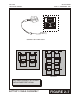
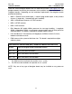
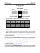
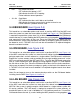
DIP SWITCH USE
on the
iDCS 500 MCP
ON (left) OFF (right)
COUNTRY SELECT SW 1 COUNTRY SELECT
COUNTRY SELECT SW2 COUNTRY SELECT
COUNTRY SELECT SW3 COUNTRY SELECT
COUNTRY SELECT SW4 COUNTRY SELECT
COUNTRY SELECT SW5 COUNTRY SELECT
4 DIGIT STATION NUMBERS SW6 3 DIGIT STATION NUMBERS
4 DIGIT STATION GROUPS SW7 3 DIGIT STATION GROUPS
4 DIGIT TRUNK NUMBERS SW8 3 DIGIT TRUNK NUMBERS
!
Switches 1 through 4 select the country the system is installed in.
4 3 2 1 Country
OFF OFF OFF OFF Korea
OFF OFF OFF ON USA
OFF OFF ON OFF UK
OFF OFF ON ON Italy
OFF ON OFF OFF Australia
OFF ON OFF ON New Zealand
OFF ON ON OFF Holland
OFF ON ON ON Denmark
!
Switch 5 reserved.
!
These DIP switches will not take effect unless the switches are set in the wanted
position and the system memory is cleared manually by using the Memory Backup
switch.
Install the SmartMedia card. Install daughter board(s). Set the MCP DIP switches on the
card to the desired positions.
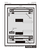
Insert MCP card in the CAB slot labeled MCP/LCP (see Figure 3–1). Push firmly at the
top and bottom of the card to ensure that it is fully inserted into the back plane
connector. To prevent accidental damage to the MCP card, the MCP/LCP connector on
the back plane is positioned to mate only with the MCP or LCP card. Other interface
cards will not mate with this connector and the MCP card will not mate with any other
connector. NOTE: Do not insert this card with system power ON.
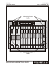
3.2 SCP CARD
(see Figure 3–3)
The iDCS 500 Expansion Control Processor (SCP) is used when the system is expanded
to more than one cabinet. In a multiple cabinet system the SCP becomes the processor