
User guide


iDCS 500 INSTALLATION
TECHNICAL MANUAL PART 3 NOVEMBER 2001
3.6
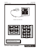
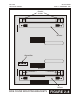
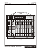
3.3 LCP CARD
(see Figure 3–4)
The iDCS 500 Local Control Processor (LCP) is used when the system is expanded to
more than one cabinet. The LCP is the processor for the second and or third iDCS 500
cabinet(s) and communicates via a high-speed data link to the MCP. The LCP installs in
the MCP/LCP slot in the second or third cabinets of a multiple cabinet system. The SCP
can have three daughter boards installed as indicated by the table below.
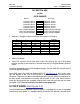
SWITCH CONTROL PROCESSOR (LCP) DAUGHTER BOARD CAPABILITIES
Position Types of Daughter Boards allowed per position
MCP – D1 MFM, RCM
MCP – D2 MFM, RCM and MISC
MCP – D3 MFM, RCM
NOTE: Only one of any type of daughter board may be installed on any processor
card.
Push firmly at the top and bottom of the card to ensure that it is fully inserted into the
back plane connector. Connect the iDCS 500 Inter-Processor Connection cable (CIC)
to the front of the LCP. Connect the opposite end of the CIC to the connector on the
front of the MCP. Connect the second CIC in a similar manner between LCP cards.
The DIPC is supplied with the LCP.
NOTE: Do not insert this card with system power ON.
To prevent accidental damage to the LCP card, the MCP/LCP connector on the back
plane is positioned to mate only with the MCP or LCP card. Other interface cards will
not mate with this connector and the MCP or LCP card will not mate with any other
connector.
There are twelve (12) LED indicators on the front of the LCP card. The uses are as
follows:
• TX: LCP HDLC TX (Transmit) Status
OFF indicates that there is no link from the LCP card
ON indicates that the link from the LCP card is being set up
Flicker indicates a message has been transmitted.
• RX: LCP HDLC RX (Receive) Status
OFF indicates that there is no link from the LCP card
ON indicates that the link from the LCP card is being set up
Flicker indicates a message has been received.