
User Manual


English - 5
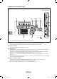
What is HDMI?
- “High Denition Multimedia interface” allows the transmission of high denition digital video data and multiple channels
of digital audio.
-
The HDMI/DVI terminal supports DVI connection to an extended device with the appropriate cable (not supplied). The
difference between HDMI and DVI is that the HDMI device is smaller in size, has the HDCP (High Bandwidth Digital Copy
Protection) coding feature installed, and supports.
DVI IN(HDMI2) [R-AUDIO-L]
- DVI audio outputs for external devices.
Supported modes for HDMI/DVI and Component.
480i 480p 576i 576p 720p 1080i
HDMI/DVI 50Hz X X X O O O
HDMI/DVI 60Hz X O X X O O
Component O O O O O O
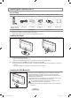
4 AUDIO OUT [R-AUDIO-L]
Connect RCA audio cables to AUDIO OUT [R-AUDIO-L] on the rear of your set and the other ends to corresponding audio in
connectors on the Amplier or DVD Home Theatre.
5
ANT IN
To view television channels correctly, a signal must be received by the set from one of the following sources:
- An outdoor aerial / A cable television network / A satellite network
6
SERVICE
LE26A466, LE26A467
Connector for SERVICE only.
LE32A466, LE32A467, LE32A465, LE37A466, LE37A467, LE40A466, LE40A467, LE40A465
Connect this to the jack on the optional wall mount bracket. This will allow you to adjust the TV viewing angle using your
remote control.
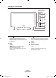
7
COMMON INTERFACE Slot
- When not inserting “CI CARD” in some channels, “Scrambled Signal” is disp
layed
on the screen.
- The pairing information containing a telephone number, CI CARD ID, Host ID and
other information will be displayed in about 2~3 minutes. If an error message is
displayed, please contact your service provider.
-
When the channel information conguration has nished, the message “Updating
Completed” is displayed, indicating that the channel list is now updated.
You must obtain a CI CARD from a local cable service provider. Remove the CI
CARD by carefully pulling it out with your hands since dropping the CI CARD may cause damage to it.
Insert the CI-Card in the direction marked on it.
The place of the COMMON INTERFACE Slot may be different depending on its model.
8
SERVICE
- Connector for SERVICE only.
9
S-VIDEO or VIDEO / R-AUDIO-L
- Connect RCA or S-VIDEO cable to an appropriate external A/V device such as VCR, DVD or Camcorder.
-
Connect RCA audio cables to “R-AUDIO-L” on your set and the other ends to corresponding audio out connectors on
the A/V device.
0
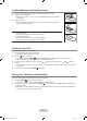
HEADPHONES JACK
- Headphone may be connected to the headphone output on your set. While th
e head phone is connected, the sound
from the built-in speakers will be disabled.
➣
➣
-
-
-
➣
➣
➣
BN68-01424M-00Eng.indb 5 2008-08-19 �� 2:58:54