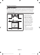
Electric Range installation manual imagine the possibilities Thank you for purchasing this Samsung product. Install_NE58H9970WS_AA_AC_DG68-00594B-00_EN+CFR.
contents PREPARING TO INSTALL THE RANGE 3 3 3 4 4 5 7 About this section For your safety Remove packaging Prepare tools & Parts Checking the installation site To avoid breakage CONNECTING THE POWER 8 10 13 16 Step 1. M eeting electrical connection requirements Step 2. Accessing the power cord connection Step 3. I nstalling the power cord Step 4. Installing the conduit Step 5.
preparing to install the range ABOUT THIS SECTION READ THESE INSTRUCTIONS COMPLETELY AND CAREFULLY. Important note to the installer • Remove all packing materials from the oven compartments before connecting the electrical supply to the range. • Observe all governing codes and ordinances. • Be sure to leave these instructions with the consumer. Important note to the consumer Keep these instructions for the local electrical inspector’s use.
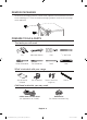
REMOVE PACKAGING Remove the packaging materials. Remove the supporter frame located on the back of the cooktop glass. Failure to remove packaging materials could result in damage to the appliance.
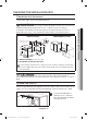
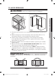
CHECKING THE INSTALLATION SITE Clearances and dimensions To install the range, refer to the following figure. CAUTION SLIDE-IN CUTOUT 3" Hatched Faces should be flat and leveled. 4-1/2" 36"~36-3/4" 23-3/16" 24" 26-5/16" 28-5/8" 24-11/16" 1/2" min. 1" min. 3" 23-3/16" 35-7/8" 31" FREESTANDING CUTOUT 3" 25" 6" 6" 6-5/16" 29-15/16" 3" 25" B A 24" A B A 48" 26-5/16" A : Cabinet opening min 30" (76.
Minimum dimensions IMPORTANT To eliminate the risk of burns or fire caused by reaching over heated surface units, avoid having cabinet storage space located above the surface units. If you have cabinet storage space over the heating elements, you can reduce the risk by installing a range hood that projects horizontally a minimum of 5 inches beyond the bottom of the cabinets.
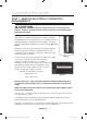
TO AVOID BREAKAGE CAUTION CAUTION Do NOT lift or handle the unit by the cooktop glass. C2 C1 C3 Fig. 1 1. The counter top around the cut-out should be flat and leveled (see hatched area on Fig. 1). 2. Before installing the unit, measure the heights of the two cabinet sides (C1~C4), front and back (See Fig. 1) from the floor to the top of the counter. 3.
connecting the power STEP 1. MEETING ELECTRICAL CONNECTION REQUIREMENTS CAUTION CAUTION For personal safety, do not use an extension cord with this appliance. Remove the house fuse or open the circuit breaker before beginning installation. This appliance must be supplied with the proper voltage and frequency, and be connected to an individual, properly grounded branch circuit, protected by a circuit breaker or fuse having amperage as specified on the rating plate.
A range cord rated at 40 amps with 125/250 minimum volt range is required. A 50 amp range cord is not recommended but if used, it should be marked for use with nominal 13⁄8" diameter connection openings. Care should be taken to center the cable and strain relief within the knockout hole to keep the edge from damaging the cable. • Because range terminals are not accessible after the range is in position, a flexible service conduit or cord must be used.
Specified rating of power-supply-cord kit and circuit protection 120/240 volts 3-wire 120/208 volts 3-wire Specified rating of power-supplycord kit and circuit protection, Amps 8750 - 16500 7801 - 12500 40 or 50 A Range rating, watts Diameter (inches) of range connection opening Power cord Conduit 13/8" 11/8" This appliance must be supplied with the proper voltage at the proper frequency and must be connected to a dedicated, properly grounded branch circuit protected by a 40 amp or larger circui
Installing a 3-wire power cord WARNING WARNING The neutral or ground wire of the power cord must be connected to the neutral terminal located in the center of the terminal block. The power leads must be connected to the lower left and the lower right terminals of the terminal block. 2. Insert the 3 terminal screws through each power cord terminal ring and into the lower terminals of the terminal block.
Installing a 4-wire power cord WARNING WARNING The neutral wire of the supply circuit must be connected to the neutral terminal located in the lower center of the terminal block. The power leads must be connected to the lower left and the lower right terminals of the terminal block. The 4th grounding lead must be connected to the frame of the range with the ground plate and the ground screw. 1. Remove the 3 lower terminal screws from the terminal block.
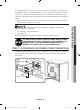
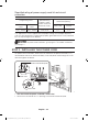
STEP 4. INSTALLING THE CONDUIT Remove the conduit connection plate and rotate it as shown below. The conduit hole (11/8") must be used. 11/8" 13/8" 11/8" 1. Prepare the conduit cord as shown in Figure 1. 2. Install the conduit cord as shown in Figure 2. 1" Figure 1 3/8" 31/2" 3 wire Figure 2 1" 3/8" 31/2" 4 wire Knockout surface Conduit connection plate Ring Body Strain relief For conduit installations, insert the strain relief (not included) into the conduit hole (11/8").
Installing a 3-wire conduit • Aluminum building wire may be used but it must be rated for the correct amperage and voltage. Connect the wires as described below. • The wire you use, the location and enclosure of splices, etc., must conform to good wiring practices and local codes. 1. Loosen the 3 lower terminal screws from the terminal block. 2. Insert the center bare wire (white/ neutral) tip through the bottom center terminal block opening.
Installing a 4-wire conduit • Aluminum building wire may be used but it must be rated for the correct amperage and voltage to make the connection. Connect the wires as described below. • The wire you use, the location and enclosure of splices, etc., must conform to good wiring practices and local codes. 2. Cut and discard the ground strap. Do not discard any screws. 3.
STEP 5. REPLACING THE ACCESS COVER To replace the rear access cover on the range back. Insert the double projections on the bottom of the cover into the pockets located below the opening, and then insert and tighten the rear access cover screw. English - 16 Install_NE58H9970WS_AA_AC_DG68-00594B-00_EN+CFR.
installing the range INSTALLING THE ANTI-TIP DEVICE WARNING WARNING To reduce the risk of tipping, you must secure the appliance by properly installing the Anti-Tip device packed with the appliance. Refer to the installation instructions supplied with the bracket. • If the anti-tip device is not installed properly, an adult or child stepping on or sitting on the range door could tip the range and suffer serious injuries caused by spilled hot liquids or by the range itself.
3. Check your adjustments Use a spirit level to check your adjustments. Place the level diagonally on the oven rack or surface cooktop, and confirm the range is level in the two directions shown below. 1. Check direction 1. 2. Check direction 2. If the spirit level indicates that the range is not level, adjust the leveling legs with a wrench. English - 18 Install_NE58H9970WS_AA_AC_DG68-00594B-00_EN+CFR.
FINALIZING THE INSTALLATION • Move range close enough to the opening to plug into the receptacle. • Slide the range into position ensuring that the rear left (or rear right) leg slides under the Anti-Tip bracket. • Carefully tip the range forward to insure that the Anti-Tip bracket engages the back brace and prevents tip-over. Anti-Tip bracket Leveling leg English - 19 Install_NE58H9970WS_AA_AC_DG68-00594B-00_EN+CFR.indb 19 6/7/2019 12:45:44 PM 03 INSTALLING THE RANGE • Turn on the electrical power.
Scan the QR code* or visit www.samsung.com/spsn to view our helpful How-to Videos and Live Shows For a Spanish version of this manual, visit our Website at www.samsung.com. * Requires reader to be installed on your smartphone QUESTIONS OR COMMENTS? COUNTRY CALL OR VISIT US ONLINE AT U.S.A Consumer Electronics 1-800-SAMSUNG (726-7864) www.samsung.com/us/support CANADA 1-800-SAMSUNG (726-7864) www.samsung.com/ca/support (English) www.samsung.
Manuel d'utilisation Manuel d'installation un monde de possibilités Nous vous remercions d'avoir choisi ce produit Samsung. Install_NE58H9970WS_AA_AC_DG68-00594B-00_EN+CFR.
sommaire PRÉPARATION AVANT L'INSTALLATION DE LA CUISINIÈRE 3 3 3 4 4 5 7 A propos de cette section Pour votre sécurité Retirer l'emballage Préparation des outils et des pièces Vérification du site d'installation Pour éviter toute rupture MISE SOUS TENSION 8 Étape 1 : R espect des exigences en matière de raccordements électriques Étape 2 : A ccès au branchement du cordon d'alimentation Étape 3 : Installation du cordon d'alimentation Étape 4 : Installation de la gaine Étape 5 : R emise en place du
préparation avant l'installation de la cuisinière A PROPOS DE CETTE SECTION LISEZ ENTIÈREMENT ET ATTENTIVEMENT CES INSTRUCTIONS. Note importante destinée à l'installateur • Retirez tous les éléments d'emballage des compartiments du four avant de raccorder la cuisinière à l'alimentation électrique. • Respectez tous les codes et règlements en vigueur. • Assurez-vous de laisser ces instructions à l'utilisateur.
RETIRER L'EMBALLAGE Retirez le matériel d'emballage. Retirez l'encadrement de soutien situé à l'arrière de la vitre de la table de cuisson. Tout matériel d'emballage non retiré risque d'endommager l'appareil.
VÉRIFICATION DU SITE D'INSTALLATION Dégagements et dimensions Pour procéder à l'installation de la cuisinière, reportez-vous au schéma suivant. AVERTISSEMENT DISJONCTEUR ENCASTRABLE 3" Les surfaces hachurées doivent être plates et de niveau. 4-1/2" 36"~36-3/4" 23-3/16" 26-5/16" 28-5/8" 24-11/16" 1/2" mini. 1" mini. 3" 23-3/16" 35-7/8" 31" 6-5/16" 29-15/16" 24" DISJONCTEUR NON ENCASTRABLE 3" 25" 6" 6" 3" 25" B A 24" A B A 48" 26-5/16" A : Ouverture du meuble 30" minimum (76.
Dimensions minimales IMPORTANT Pour éliminer tout risque de brûlure ou d'incendie lors de l'accès à l'espace situé au-dessus des éléments de cuisson chauds, évitez d'y aménager tout meuble de rangement. Si un meuble de rangement est situé audessus des éléments de cuisson, vous pouvez réduire le risque en installant une hotte d'aspiration assurant une protection horizontale d'au moins 5 pouces au-delà du dessous du meuble.
POUR ÉVITER TOUTE RUPTURE ATTENTION ATTENTION NE PAS lever ou manipuler l'appareil en le tenant par la vitre de la table de cuisson. C2 C4 C3 Fig. 1 1. Le plan de travail autour des découpes doit être plat et ajusté (voir la zone hachurée sur la Fig. 1). 2. Avant d'installer l'appareil, mesurez les hauteurs des deux côtés du meuble (C1 à C4), à l'avant et à l'arrière (voir Fig. 1), en partant du sol jusqu'en haut du plan de travail. 3.
mise sous tension ÉTAPE 1 : RESPECT DES EXIGENCES EN MATIÈRE DE RACCORDEMENTS ÉLECTRIQUES ATTENTION ATTENTION Pour votre sécurité, n'utilisez pas de rallonge pour brancher l'appareil. Retirez le fusible de l'installation électrique ou ouvrez le disjoncteur avant de démarrer l'installation. Cet appareil doit être alimenté par la fréquence et la tension adaptées.
Un cordon d'alimentation nominale de 40 A et de 125/250 V minimum est indispensable. Il n'est pas recommandé d'utiliser un cordon d'alimentation de 50 A, mais si toutefois vous en utilisé un, celui-ci doit être repéré pour être utilisé avec des ouvertures de connexion de diamètre nominal 13⁄8". Veillez à bien centrer le câble et le dispositif de protection contre la traction dans le trou d'éjection afin d'empêcher que le bord n'endommage le câble.
Classification de l'équipement nécessaire à la mise sous tension et de la protection du circuit Classification Diamètre (pouces) de de l'équipement l'ouverture de connexion nécessaire à la mise de la cuisinière sous tension et de la 120 / 240 volts, 120 / 208 volts, Cordon protection du circuit, Gaine 3 fils 3 fils d'alimentation ampères 11/8" 8750 - 16500 7801 - 12500 40 ou 50 A 13/8" Cet appareil doit être alimenté par la tension adaptée, à la fréquence appropriée.
Installation d'un cordon d'alimentation à 3 fils AVERTISSEMENT AVERTISSEMENT Le neutre ou le fil de terre du cordon d'alimentation doit être connecté à la borne neutre située au centre du bornier. Les conducteurs de puissance doivent être connectés aux bornes inférieure gauche et inférieure droite du bornier. Borne neutre 2. Insérez les 3 vis de borne dans les bornes inférieures Phase 1 du bornier en traversant chacune des cosses du cordon d'alimentation.
Installation d'un cordon d'alimentation à 4 fils AVERTISSEMENT AVERTISSEMENT La prise neutre du circuit d'alimentation doit être connectée à la borne neutre située au centre inférieur du bornier. Les câbles d'alimentation doivent être connectés aux bornes inférieures gauches et inférieures droites du bornier. Le 4ème câble de mise à la terre doit être connecté au bâti de la cuisinière au moyen de la plaque et de la vis de masse. 1. Retirez les 3 vis de la borne inférieure du bornier.
ÉTAPE 4 : INSTALLATION DE LA GAINE Retirez la plaque de connexion de la gaine et tournez-la comme indiqué ci-dessous. Vous devez utiliser l'orifice de la gaine (11/8"). 11/8" 13/8" 11/8" 1. Préparez le cordon de la gaine comme le montre la figure 1. 2. Installez le cordon de la gaine comme le montre la figure 2.
Installation d'une gaine à 3 fils • Un fil réalisé en aluminium peut être utilisé mais il devra être doté de l'intensité et de la tension nominales correctes. Raccordez les fils comme décrit ci-dessous. • Le fils utilisé, l'emplacement, les boîtiers de protection pour les épissures, etc. doivent être conformes aux bonnes pratiques de câblage et aux codes locaux. 1. Desserrez les 3 vis des bornes inférieures du bornier. 2.
Installation d'une gaine à 4 fils • Un fil réalisé en aluminium peut être utilisé mais il devra être doté de l'intensité et de la tension nominales correctes permettant d'établir la connexion. Raccordez les fils comme décrit ci-dessous. • Le fils utilisé, l'emplacement, les boîtiers de protection pour les épissures, etc. doivent être conformes aux bonnes pratiques de câblage et aux codes locaux. 2. Coupez et éliminez le conducteur de terre. Ne jetez aucune vis. 3.
ÉTAPE 5 : REMISE EN PLACE DU PANNEAU D'ACCÈS Pour replacer le panneau d'accès à l'arrière de la cuisinière. Insérez les deux parties en saillie situées en bas du panneau dans les orifices situés sous l'ouverture, insérez et serrez la vis du panneau d'accès arrière. Français - 16 Install_NE58H9970WS_AA_AC_DG68-00594B-00_EN+CFR.
installation de la cuisinière INSTALLATION DU DISPOSITIF ANTI-BASCULEMENT AVERTISSEMENT • Reportez-vous aux consignes d'installation fournies avec le support. • Si le dispositif anti-basculement n’est pas installé correctement, un enfant ou un adulte montant ou s'asseyant sur la porte peut faire basculer la cuisinière et provoquer de graves blessures par le renversement de liquides chauds ou par la cuisinière elle-même. Support antibasculement * approximativement 21/32" (16.
3. Vérification des réglages Utilisez un niveau à bulle pour vérifier vos réglages. Placez le niveau en diagonale sur la grille du four ou la table de cuisson et vérifiez le niveau dans les deux directions indiquées ci-dessous. 1. Vérifiez la direction 1. 2. Vérifiez la direction 2. Si le niveau à bulle indique que la cuisinière n'est pas de niveau, ajustez les pieds de mise à niveau à l'aide d'une clé. Français - 18 Install_NE58H9970WS_AA_AC_DG68-00594B-00_EN+CFR.
FINALISATION DE L'INSTALLATION Support antibasculement Pied de mise à niveau Français - 19 Install_NE58H9970WS_AA_AC_DG68-00594B-00_EN+CFR.indb 19 6/7/2019 12:45:48 PM 03 INSTALLATION DE LA CUISINIÈRE • Placez la cuisinière suffisamment près de l'ouverture pour permettre le branchement de la prise. • Positionnez la cuisinière en vous assurant que le pied arrière gauche (ou arrière droit) se place sous le support anti-basculement.
Scannez le code QR* ou rendez-vous sur le site www.samsung.com/spsn pour voir nos vidéos et démonstrations en direct d'utilisation. Pour obtenir une version espagnole de ce manuel, consultez notre site Web à l'adresse www.samsung.com. * Requiert l'installation d'un lecteur sur votre smartphone UNE QUESTION ? UN COMMENTAIRE ? PAYS TÉLÉPHONE SITE INTERNET U.S.A Consumer Electronics 1-800-SAMSUNG (726-7864) www.samsung.com/us/support CANADA 1-800-SAMSUNG (726-7864) www.samsung.