AVXWV@@_IM_E_29819-1_4.14.09.
Contents Safety Precautions ............................................................................................................ Accessories ............................................................................................................................ Selecting the Installation Location ....................................................................... Fixing the installation plate ...................................................................
Safety Precautions The following safety precautions must be taken when using your air conditioner. WARNING • Risk of electric shock can cause injury or death. • Disconnect all remote electric power supplies before servicing, installing or cleaning. • Installation must be done by the manufacturer or service agent or a similar qualified person in order to avoid a hazard. INSTALLING THE UNIT The unit should not be installed by the user. Ask the dealer or authorized company to install the units.
Safety Precautions (Continued) POWER SUPPLY LINE OR CIRCUIT BREAKER If the power cable of this air conditioner is damaged, it must be replaced by service agent or similarly qualified persons in order to avoid a hazard. The unit must be plugged into an independent circuit if applicable or connect the power cable to the auxiliary circuit breaker. An all pole disconnection from the power supply must be incorporated in the fixed wiring with a contact opening of >3mm.
CAUTION Make sure that you earth the cables. - Do not connect the earth wire to the gas pipe, water pipe, lighting rod or telephone wire. If earthing is not complete, electric shock or fire may occur. Install the circuit breaker. - If the circuit breaker is not installed, electric shock or fire may occur. Make sure that the condensed water dripping from the drain hose runs out properly and safely.
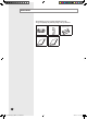
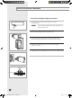
Accessories The following accessories are supplied with the indoor unit. The type and quantity may differ depending on the specifications. Installation Plate Remote Control User’s Manual Installation Manual Batteries for Remote Control E-6 AVXWV@@_IM_E_29819-1_4.14.09.
Selecting the Installation Location Indoor Unit Select a convenient location that permits the air to reach every corner of the area to be cooled. Pre-plan for easy and short routing of the refrigerant tubing and wiring to the outdoor unit. There should be no flammable gas, alkaline, substances present in the air. Avoid location where obstacles preventing good air circulation are present. Noise prevention should be considered in determining the unit's location.
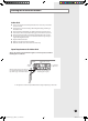
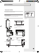
Fixing the Installation Plate Before fixing the installation plate to the wall or window frame, you must determine the position of the 65mm hole through which the cable, pipe and hose pass to connect the indoor unit to the outdoor unit. When facing the wall, the pipe and cable can be connected from the: Installation plate Pipe hole (Ø65mm) 1 2 (Unit : mm) 022/028/036 (Unit : mm) 47 74 If you fix the indoor unit to a... Follow step(s)... Wall 3. Window frame 4 to 6.
EEV Kit Installation Preparing for Installation 1 Concrete Check dimension and installation location. Insert 2 Hole in anchor Hole in plug Check installation place. By using a pattern sheet, check required installation space. Suspension bolt(3/8" or M10)-field supply ��� ��� Unit : mm 450mm X 200mm or more (Maintenance Hole) Maintenance hole must be located on the ceiling.
EEV Kit Installation (Continued) Connection of refrigerant piping & Insulation 1 Insert bot anchors, use existing ceiling supports or construct a suitable support. CAUTION Ensure the ceiling is strong enough to support the weight of the indoor unit. Before hanging the unit, test the strength of each attached suspension bolt. 2 Connect the “IN” refrigerant pipe to the outdoor unit. 3 Connect the “OUT” refrigerant pipe to each indoor unit(A, B and C).
Wiring & Assigning address A B C Room A Room B Another EEV Kit Outdoor unit 1 Connect the AC power cable and communication cable from the outdoor unit to terminal, then connect the cable to another EEV kit. 2 Connect the AC power cable and communication cable to each indoor unit (A, B and C). 3 EEV kit address should be set same with connected indoor units main address. For Example When Main address is set as “03” that connected in pipe “A”, the EEV kit “A” address should be set as “03”.
EEV Kit Installation (Continued) Function of Display The numbers which are displayed on left are the status of indoor unit checking status through communication with same outdoor unit. (If it indicates 1, 3 and 7, that means the ADDRESS of indoor unit is set to 1, 3 and 7.) The numbers which are displayed on right indicate the ADDRESS of SW01/SW02, SW03/SW04 and SW05/SW06 in sequential.
Connecting the Refrigerant Pipe There are 2 refrigerant pipes of different diameters: The smaller one is for the liquid refrigerant The larger one is for the gas refrigerant A short pipe is already fitted to the air conditioner. You may need to extend the pipe using the assembly pipe.
Cutting/Flaring the Pipes 1 Make sure that you prepared the required tools. (pipe cutter, reamer, flaring tool and pipe holder) 2 If you want to shorten the pipe, cut it using a pipe cutter ensuring that the cut edge remains at 90° with the side of the pipe. There are some examples of correctly and incorrectly cut edges below. Oblique Rough Burr 3 To prevent a gas leak, remove all burrs at the cut edge of the pipe using a reamer. 4 Carry out flaring work using flaring tool as shown below.
Performing Leak Test & Insulation Leak test LEAK TEST WITH NITROGEN (before opening valves) In order to detect basic refrigerant leaks, before recreating the vacuum and recirculating the R410A, it’s responsible of installer to pressurize the whole system with nitrogen (using a pressure regulator) at a pressure above 4.1MPa (gauge). C D LEAK TEST WITH R410A (after opening valves) Before opening valves, discharge all the nitrogen into the system and create vacuum.
Performing Leak Test & Insulation (Continued) 8 Select the insulator of the refrigerant pipe. Insulate the gas side and liquid side pipe referring to the thickness according to the pipe size. The thickness according to the pipe size is a standard of the indoor temperature of 27°C and humidity of 80%. If installing in an unfavorable conditions, use thicker one. Insulator’s heat-resistance temperature should be more than 120℃. Pipe size (mm) Minimum thickness of insulator (mm) PE foam EPDM foam Ø6.
Installing and Connecting the Drain Hose of the Indoor Unit When installing the drain hose for the indoor unit, check if condensation draining is adequate. When passing the drain hose through the 65-mm hole drilled in the wall, check the following: 5cm less Ditch The hose must NOT slant upwards. The end of the drain hose must NOT be placed under water. Do NOT bend the hose in different directions. Keep a clearance of at least 5cm between the end of the hose and the ground.
Wiring Work Power and communication cable connection 1 Before wiring work, you must turn off all power source. 2 Indoor unit power should be supplied through the breaker(MCCB, ELB) separated by the outdoor power. 3 The power cable should be used only copper wires. 4 Connect the power cable{1(L), 2(N)} among the units within maximum length and communication cable(F1, F2) each. 5 Connect V1, V2(for DC12V) and F3, F4(for communication) when installing the wired remote control.
Specification of electronic wire Power supply MCCB ELB Max : 242V Min : 198V XA X A, 30mmA 0.1 sec Communication cable Power cable Earth cable 2.5mm2 2.5mm2 0.75~1.5mm2 Unit Decide the capacity of ELB and MCCB by below formula. Model AVXWV 022 028 036 056 071 The capacity of ELB, MCCB X [A] = 1.25 X 1.1 X ∑Ai X : The capacity of ELB, MCCB ∑Ai : Sum of Rating currents of each indoor unit. Refer to each installation manual about the rating current of indoor unit.
Wiring Work (Continued) CAUTION Select the power cable in accordance with relevant local and national regulations. Wire size must comply with local and national code. For the power cable, use the grade of H07RN-F or H05RN-F materials. You should connect the power cable into the power cable terminal and fasten it with a clamp. The unbalanced power must be maintained within 10% of supply rating among whole indoor units.
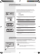
Indoor Unit Setting 1 Before installing the indoor unit, assign an address to the indoor unit according to the air conditioning system plan. 2 The address of the indoor unit is assigned by adjusting MAIN(SW01, SW02) and RMC(SW03, SW04) rotary switches. SW05 SW01 SW02 SW03 SW04 SW06 Cover PCB SW07 The designs and shape are subject to change according to the model. Setting Main Address The MAIN address is for communication between the indoor unit and the outdoor unit.
Additional Functions �� �� �� �� No. SW05 ���� �� �� �� �� ���� ���� OFF - - - K2 Centralized controller Not use Use K3 - - - K4 - - - Function ON OFF K5 Heating Current Temperature Compensation +2°C +5°C K6 Filter Time 1,000 hours 2,000 hours K7 - - - K8 - - - Function ON OFF K9 Indoor Expansion Valve For Heating Stop Fix 80 step 0 or 80 step K10 Wired Remocon Group Master Not use Use K11 External control Not use Use K12 - - - No.
Final Checks and User Tips To complete the installation, perform the following checks and tests to ensure that the air conditioner operates correctly. 1 Check the following: Strength of the installation site Tightness of pipe connection to detect gas leak Electric wiring connection Heat-resistant insulation of the pipe Drainage Grounding conductor connection Correct operation (follow the steps below) 2 Press the button and check the following: The indicator on the indoor unit lights up.
Troubleshooting Detection of errors If an error occurs during the operation, one or more LED flickers and the operation is stopped except the LED. If you re-operate the air conditioner, it operates normally at first, then detect an error again.
Indicators Abnormal conditions Remarks Self-diagnostic error (including the indoor unit not detected) 1. Error of electronic expansion valve close 2. Error of electronic expansion valve open 3. Breakaway of EVA OUT sensor 4. Breakaway of EVA IN sensor Displayed on appropriate indoor unit which is operating Displayed on outdoor unit 5. Breakaway of COND MID sensor 6. 2nd detection of refrigerant completely leak 7. 2nd detection of high temperature COND 8. 2nd detection of high temperature DISCHARGE 9.
"EEE Yönetmeliğine Uygundur" "This EEE is compliant with RoHS" AVXC1@@_IM_E_29824-1_5.05.09.
INSTALLATION MANUAL Wall-mounted Type Series Vivace Type : AVXWV Air Conditioner E DB98-29819A(1) AVXWV@@_IM_E_29819-1_5.08.09.