DHW Tank NH080PHXEA NH160PHXEA NH200WHXEA NH300WHXEA NH200WHXES NH300WHXES E S F I P D DB98-32034A(2) ENGLISH DEUTSCH Air to Water Heat Pump - Hydro Unit PORTUGUÊS ITALIANO FRANÇAIS Indoor Unit ESPAÑOL INSTALLATION MANUAL
Contents Safety precautions . . . . . . . . . . . . . . . . . . . . . . . . . . . . . . . . . . . . . . . . . . . . . . . . . . . . . . . . . . . . . . . . . . Product specifications . . . . . . . . . . . . . . . . . . . . . . . . . . . . . . . . . . . . . . . . . . . . . . . . . . . . . . . . . . . . . . . Typical application examples . . . . . . . . . . . . . . . . . . . . . . . . . . . . . . . . . . . . . . . . . . . . . . . . . . . . . . . . Main components . . . . . . . . . . . . . . . . .
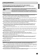
Safety precautions WARNING ENGLISH All materials supplied to this manual are indispensable for the safety of equipment. Users shall establish appropriate safety and health practices and determine the applicability of regulatory limitation based on following descriptions prior to use. • Always disconnect the air to water heat pump from the power supply before servicing it or accessing its internal components. • Verify that installation and testing operations are performed by qualified personnel.
Safety precautions (Continued) POWER SUPPLY LINE, FUSE OR CIRCUIT BREAKER Always make sure that the power supply is compliant with current safety standards. Always install the air to water heat pump in compliance with current local safety standards. Always verify that a suitable grounding connection is available.
ENGLISH Product specifications Accessories Installation Manual(1) User’s Manual(1) Pattern Sheet(1) Service Valve(2) Wall Mounting Bracket(1) Remote Controller Wire(1x15m) (1) Temperature sensor for DHW Tank(1x15m) (1) Cover Controller (1) Ring band (1) E-5
Product specifications (Continued) Specifications Type Power Source Operating Range Operating Range [Water] Electric Heater Dimensions Weight E-6 0~32 0~32 5~25 5~25 °C 15~55 15~55 kW 6 7 8 11 14 16 kg/min 17.0 20.5 23.0 31.5 40.1 45.9 kPa -/53 -/51 -/45 -/64 -/59 -/54 No of speed - High High High High High High Output W 180 200 Brazing plate E.S.
Indoor unit Subsidiary materials Capacity EEV Kit Duct Wall mounted Air to Water unit Slim Duct Vivace Neo-Forte Hydro Unit 2.2~5.6kW 2.2~7.1kW 2.2~7.1kW 8/16kW - MXD-A13K116B MXD-A13K200B MXD-A16K200B MXD-A13K216B MXD-A13K300B MXD-A16K231B MXD-A16K300B ≤3.6kW 1room + ≥5.6kW 1room ≤3.6kW x 2room ≥5.6kW x 2room ≤3.6kW 2room + ≥5.6kW 1room ≤3.6kW x 3room ≤3.6kW 1room + ≥5.6kW 2room ≥5.6kW 3room - EEV kit for 2/3 room MXJ-YA1509K (≤15.
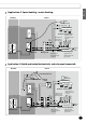
Typical application examples When the SAMSUNG Air-to-Water Heat Pump system is used in series with another heat source (e.g. gas boiler). Ensure that the return water temperature not exceed 55°C. SAMSUNG shall not be held liable for any damage resulting from not observing this rule. The below examples are for illustration purposes only.
ENGLISH Application 3: Space heating + water heating Outdoor Indoor Room Controller 45°C Supply Header Our Supply Range Return Header Radiators or Convectors DHW Tank Load Pump #1 Load Pump #2 [Application #2] Thermostatic & Balancing Valves [Application #3] Room Thermosat & Actuators 40°C Supply Header Return Header Outdoor unit Under-Floor Heating Coils Mixing Tank Hydro-unit [Application #1] Zone Thermostat & 2way Valve Bypass valve [Application #4] Differential Pressure bypass Valve
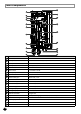
Main components 21 1 20 2 3 4 19 18 5 6 17 7 16 8 9 15 14 13 10 12 11 No. Name Note 1 Air vent 3/8” 2 Backup heater thermal fuse Thermal cut out 94°C (+0, -6°C) 3 Backup heater thermostat Disc. 65°C ±4°C 4 Backup Heater Element Incoloy 800, 4/6kW, 230V AC 50Hz 5 Drain Hose BSPP male 3/8” 6 Flow switch 12/16LPM ±1.
8 ENGLISH Functional diagram 7 6 Tw2 14 15 Tw3 16 Tr1 3 5 Ref' In 4 10 Ref' Out 9 Tr2 17 Tw1 13 11 2 12 1 Water Out No. 1 Water In Note Service valve(R) 2 Strainer 3 Flow switch 4 Heat exchanger 5 EEV kit 6 Backup heater 7 Pressure relief valve 8 Air-vent valve 9 Water pump 10 Expansion tank 11 Manometer 12 Service valve(L) 13 Water temp. sensor 1 14 Water temp. sensor 2 15 Water temp. sensor 3 16 Refrigerant temp. sensor 1 17 Refrigerant temp.
Dimensional drawing 314.6 39.2 22.0 850.0 510.0 125.0 104.0 E-12 103.7 490 78.5 131.
Installation of the indoor unit The indoor unit should be installed indoors and meet the following conditions. Installation site should be sheltered from frost. In area with suitable space for servicing. A place with adequate ventilation. Where there is no risk of leakage of flammable gases. There is a provision for condensate drain and pressure relief valve blow-off. The wall for installation is a flat, vertical and non-combustible wall, capable of supporting the operation weight of the unit.
Installing the unit (Continued) Mounting the indoor unit Handle A minimum of two people should lift the unit by the handles and not by the drain pan or pipe work. Drill 6 holes from the pattern sheet for fixing the wall bracket and unit. After completing holes, detach the pattern sheet. Fix the wall-mount-bracket to the wall using appropriate plugs and screws(Use over M8 6 screws). Hang the indoor unit on an wall-mount-bracket and fix a front cabinet on the unit by using 4 screws.
Refrigerant pipe work For all guide lines, specifications regarding refrigerant pipe work between the indoor unit and the outdoor unit, please follow the outdoor unit installation manual. Gas pipe (O.D.) Liquid pipe (O.D.) Tightening Torque Final Torque 15.9mm(5/8 inch) 9.5mm(3/8 inch) 400kg·cm 450kg·cm Outdoor unit 15.9mm(5/8 inch) 9.5mm(3/8 inch) 700 kg·cm 750kg·cm Indoor unit When connecting the refrigerant pipes, always use 2 wrenches/spanners for tightening or loosening nuts.
Pipe work (Continued) Water pipe work The hydro unit is equipped with components listed on the table below. The hot and cold water supply connections are clearly marked on the unit with labels. And service valves are provided. Whole water plumbing system including Hydro unit shall be installed by a qualified technician and must comply with all relevant European and national regulations. Allowable water pressure of hydro unit is maximum 3.0 bar. 2 service valves are provided with the Hydro unit.
ENGLISH Flushing and air-purging When filling water, the following start-up procedure should be followed. 1. All system components and pipes must be tested for the presence of leaks. 2. Preparation of a make-up water assembly or Flushing unit is recommended for installation and service. 3. Before connecting pipes to the hydro unit, Flush water pipes clean to remove contaminants during 1 hours using a flushing unit or tap water pressure if it is adequate (at 2 to 3 bar) 4.
Pipe work (Continued) The water volume and expansion vessel pressure The unit is equipped with an expansion vessel of 8 litres which has a default pre-pressure of 1 bar. To ensure correct operation of the unit, the pre-pressure of the expansion vessel might need to be adjusted and the minimum and maximum water volume must be checked. Norminal ax . Hydraulic Head Loss(mH2O) To secure enough water flow rate, set water pump speed as “Max.”. The standard pressure drop of the unit is 30~35 kPa.
ENGLISH Setting the pre-pressure of the expansion vessel When it is required to change the default pre-pressure of the expansion vessel(1 bar), keep in mind the following guidelines: Use only dry nitrogen to set the expansion vessel pre-pressure. Inappropriate setting of the expansion vessel pre-pressure will lead to malfunction of the system. Therefore, the pre-pressure should only be adjusted by a licensed installer. Expansion Vessel capacity (Liter) 14.00 12.00 10.00 Norminal [Lit] 8.
Pipe work (Continued) Charging water After installation is completed the following procedures shall be used to charge water into the hydro unit. Connect water lines to water connections of hydro unit. The air-vent valve shall be opened at least 2 turns and drain valves shall be closed. Open the service valve in the water supply connection. Water pressure of supply line shall be over 2.0 bar for good charging work. Stop water supply when the pressure gauge of hydro unit indicates 2.0 bar.
A pressure relief valve is integrated on heater vessel of hydro unit and shall work in abnormal condition for protecting the hydro unit. The pressure relief valve will operate releasing the pressure by flowing out some water through the drain hose. Make certain that the discharged water out of drain pan can not contact any electrical parts.
Wiring work Field-supplied electrical components such as power switch, circuit breakers, wires, terminal blocks, etc must be properly chosen with compliance with national legislation or regulation. Switch off the power supply before making any connections. All field wiring and components must be installed by a licensed electrician. Use a dedicated power supply. All power connections must be protected from dew condensation by thermal insulation. The system shall be earthed.
ENGLISH Wiring diagram E-23
Wiring work (Continued) Selecting solderless ring terminal Select a solderless ring terminal of a connecting power cable based on a nominal dimensions for cable. Cover a solderless ring terminal and a connector part of the power cable and then connect it. Silver solder Nominal Nominal B D d1 E F L d2 t dimensions dimensions Standard Standard Standard Standard Allowance Allowance Allowance Allowance for cable for screw dimension dimension dimension Min. Min. Max. dimension Min.
ENGLISH Types of allowable current Conductors of supply cord shall have a nominal cross-sectional area not less than that shown in the table below. Minimum cross-sectional area of conductors Rated current of appliance (A) ≤0.2 Nominal cross-sectional area (mm2) Tinsel corda ≤0.2 and ≤3 0.5a >3 and ≤6 0.75 >6 and ≤10 1.0(0.75)b >10 and ≤16 1.5(1.0)b >16 and ≤25 2.
Wiring work (Continued) Connection of the power supply and communication cable Description No. of wires Main power Max. A 2+ground 32A 2 6A Communication Thickness Supply Scope 4.0mm2 H05RN-F or H07RN-F 0.
ENGLISH Connecting the power terminal Connect the cables to the terminal board using the solderless ring terminal. Use certified and reliable cables. Connect the cables with the torque chart as below. If the terminal is loose, fire may occur caused by arc. If the terminal is connected too firmly, the terminal may be damaged. External force should not be applied to the terminal block and wires. The cable ties to fasten the wire should be an incombustible material, V0 or above.
Wiring work (Continued) Connection of the backup heater power supply Do not use a power supply shared by other appliances. Each components for outdoor unit, indoor unit, backup heater and booster heater has the dedicated power supply. Heater capacity (kW) ELCB capacity (A) NH080PHXEA Model 4 30 NH160PHXEA 6 40 DHW tank(200 or 300) 3 20 Circuit Breaker(ELCB, ELB, MCCB etc.)s written above are already included in the hydro unit.
ENGLISH Connection of the thermostat Description Room Thermostat for weather control No. of wires 4 N L C1 H1 Thickness Supply Scope 22mA > 0.75mm2 Field supply (230V~, Input) Process Thermostat 1 Thermostat 2 N L C1 H1 Max. A Thermostat -Weather controller - Changeover (Heating and Cooling) -230V AC -4 wires 1. Before the installation, hydro unit should be turned off. 2. Using the appropriate equipment to correct position of terminal block as shown on the diagram. 3.
Wiring work (Continued) Connection of the 3-way valve Description No. of wires Max. A Diverting type 3way valve 4 22mA 3-way diverting valve for water tank -Diverting type -230V AC Thickness 0.75mm2 H05RN-F or H07RN-F Supply Scope Field supply (230V~, Output) N L1 L When water pass to floor heating Process N 1. Before the installation, hydro unit should be turned off. 2. Using the appropriate equipment to correct position of terminal block as shown on the diagram. 3.
Troubleshooting ENGLISH If the unit has some problem to work properly, the LED on hydro unit will flash and some error codes will be displayed on the controller. The following table described the explanation of error codes on the LCD display. Thermistor Check its resistance. 10kohm@24°C (Hydro unit), 220kohm@24°C (DHW Tank, Solar) Check its location as shown at the diagram. Check its contact status with pipe.
Troubleshooting (Continued) Communication Display Explanation Abnormal communication B/W Wired remote controller & Hydro unit Communication tracking error B/W Wired remote controller & Hydro unit FRAM Read/Write Error(Wired remote controller data error) E601, E604 E654 • Wrong data transmit B/W micom & IC07(eeprom) E-32
ENGLISH Water pump &flow S/W Display Explanation Flow S/W “OFF” error (Condition : Flow switch signal is off during 10seconds when the water pump signal is ON) Flow S/W “ON” error (Condition : Flow switch signal is on during 10seconds when the water pump signal is off) Tw2 Tw3 Tr1 Ref' In Ref' Out Tr2 Tw1 Water Out Water In E911 • Water pump ON ( Flow S/W off ) Water flow>12 LPM(NH080PHXEA) >16 LPM(NH160PHXEA) • Water pump ON ( Flow S/W off ) : NOT enough water flow Water flow>12 LPM(NH080PHXEA)
DHW tank Safety information (Before installing an DHW Tank, please read this manual thoroughly to ensure that you know how to safely and efficiently install a new appliance.) WARNING • If you don’t follow the safety precautions, you may get the risk of serious wound or death. The installation must be done by the manufacturer or its service agent or a qualified person in order to avoid a hazard. - Installation by an unqualified person may cause a water leakage, electric shock or fire and so on.
SAMSUNG Eco Heating system with SAMSUNG DHW tank is designed to withstand SAMSUNG durability and reliability requirements. We cannot guarantee neither good operation nor reliability of total system with other brand tanks. The piping, valves and system configuration of DHW tank system should be followed a relevant local or national regulations. A pressure relief valve in accordance with an opening pressure of max. 0.9MPa should be connected.
DHW tank (Continued) Main components Standard 14 1 9 3 12 6 8 10 11 5 7 2 1 4 13 Solar Connected 14 9 1 3 12 6 10 11 5 8 7 2 1 4 13 No. Note No. Note 1 Top and bottom dome (pressure vessel) 2 Cylinder (pressure vessel) 3 Outer casing 9 4 Base 10 Thermistor pocket Heating element 2.
ENGLISH Outlook diagram 1 Standard 2 3 4 5 1 Solar Connected 6 2 7 3 4 5 No.
DHW tank (Continued) Accessories Leg (3) E-38 Anode bar (1) Conduit (1)
ENGLISH Water tank specifications Detailed information for the DHW Tank are described in the following table. There are 4 types of DHW tank by size and operating ways. Unit Pressure vessel Volume capacity Heating coil for Solar Insulation Solar Connected NH300WHXEA litres 198 287 INCOLOY 825 1P, 230~, 50 Duplex LDX 2101 m 0.71 2 m 2 - - - - Material quality Thickness 287 2.
DHW tank (Continued) Space requirements Positions of water inlet and outlet pipe are affected by the layout of DHW Tank. The layout of pipes and other components except DHW tank are the responsibility of installers. The DHW Tank must be laid out in accordance with the illustrations as below to prevent any water leakage and malfunction. Observe the clearances and dimensions as seen below during installing the water tank. Note The installation space mentioned above is minimum suggested clearance.
ENGLISH Piping diagram The product must be installed without any water leakage. Please verify that the DHW tank and other components are properly installed and reinstall them if necessary. - Use certified components and the correct tools. - Keep adequate space for the installing.
DHW tank (Continued) System configuration For the reliable performance and durability, all parts as listed below ,including a relief valve, an expansion vessel, a drain valve and pressure reducing valve , should be installed according to each national or regional standards. They are not supplied by SAMSUNG.
ENGLISH Wiring diagram Turn on the DHW tank and hydro unit after completing electric wiring works. Do not disassemble the wirings out of the unit while the unit is operating. Circuit breaker shall be installed for safety and maintenance . Make sure of a earthing. Do not connect the earth wire to the gas pipe, water pipe, lighting rod or telephone wire. If earthing is incomplete, electric shock or fire may occur. 40.4 66T 1 1 4 4 2 DATE CODE CAL LOT NO. 59T 4117 2 59T N ø5.
DHW tank (Continued) Switch box layout DHW tank temp.
ENGLISH Electrical connections Procedure Switch off the power supply before making any connections. Use a thermal grease in thermistor pocket after installing electric connections. Connections to be made in the electrical box of DHW tank 1. Connect the booster heater power supply and thermal protection cable. 2. Make sure to ensure strain relief of the cable. Connections to be made in the electrical box of indoor units 3. Mount the prewired contactor (K3M) and circuit breaker (F2B).
DHW tank (Continued) Power connection 1 phase 230V~ Circuit breaker Earth cable (U-Trap) Power cable Communication cable between indoor and outdoor units Earth F1 N L N L N L Communication cable F2 1 phase 1 phase 230V~ 230V~ Hydro unit DHW Tank Water circuit connection 1. Connect the water inlet and water outlet. 2. Connect the hot and cold water supply tubes. 3. Connect the pressure relief valve (field supply, opening pressure maximum 10 bar) and drain.
ENGLISH Troubleshooting IMPORTANT: All maintenance or repair work must be executed by an approved installer. Problem Hot water is not coming out. Heating is not working Water is not warm enough Safety valve(SV) is dripping. Leak warning outlet is dripping. Other problems, or if none of the above solves the problem. Possible cause Solution Check if there is any power on the power No power supply to the water heater supply terminal on the thermostat.