Ed.
COPYRIGHT This manual is proprietary to SAMSUNG Electronics Co., Ltd. and is protected by copyright. No information contained herein may be copied, translated, transcribed or duplicated for any commercial purposes or disclosed to the third party in any form without the prior written consent of SAMSUNG Electronics Co., Ltd. TRADEMARKS is the trademark of SAMSUNG Electronics Co., Ltd. Product names mentioned in this manual may be trademarks and/or registered trademarks of their respective companies.
OfficeServ 7100 Installation Manual INTRODUCTION Purpose OfficeServ 7100 is the most suitable system for offices using circuit lines with 10 to 25 subscribers. This manual describes the condition for OfficeServ 7100 system installation and how to install, inspect and operate the system. Document Content and Organization This document consists of eight chapters, and abbreviations as follows: CHAPTER 1.
Ошибка! Стиль не определен. CHAPTER 7. Connecting Stations and Additional Equipment This chapter describes how to connect various stations and additional equipment, such as analog/digital phones, door phones and door locks, to the OfficeServ 7100 system. CHAPTER 8. Starting the System This chapter describes items to check before starting the OfficeServ 7100 system, the procedure for starting the system, and the procedure for testing whether the system is normally operating after startup.
OfficeServ 7100 Installation Manual Reference OfficeServ 7100 System Manual This document introduces OfficeServ 7100 and describes the system information, such as hard configuration, specification, and functions, necessary for this system. OfficeServ 7100 Programming Manual This document describes how to use the MMC program to change the OfficeServ 7100 system setting by using a phone. Revision History EDITION DATE OF ISSUE REMARKS 00 08. 2006. Original Draft 01 01.2007. Safety, VM and Router etc.
Ошибка! Стиль не определен. This page is intentionally left blank. IV © SAMSUNG Electronics Co., Ltd.
OfficeServ 7100 Installation Manual SAFETY CONCERNS For product safety and correct operation, the following information must be given to the operator/user and shall be read before the installation and operation. Symbols Caution Indication of a general caution Restriction Indication for prohibiting an action for a product Instruction Indication for commanding a specifically required action © SAMSUNG Electronics Co., Ltd.
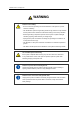
Ошибка! Стиль не определен. Warning WARNING Caution for Grounding - Do not connect the grounding wire of the OfficeServ 7100 system to a power conduit of a building - The standards for power and grounding should comply with the country standard and the pertinent work should be conducted according to the country standard. - External grounding is required to prevent human injuries or system damages caused by lightning, static electricity, or voltage surge.
OfficeServ 7100 Installation Manual Caution CAUTION Caution for Installation Only a trained service staff can install the OfficeServ 7100 system. The equipment intended only for installation in a RESTRICTED ACCESS LOCATION Caution for the connection of External Batteries Do not connect an external AC power until the battery and the system is completely disconnected. To do so may cause electric shock to the constructor or the system.
Ошибка! Стиль не определен. Separation of TNV and SELV - Pluggable A The separate protective earthing terminal provided on this product shall be permanently connected to earth. (Instruction) Telephone line cord To reduce the risk of fire, use only No. 26 AWG or larger (e.g., 24 AWG) UL Listed or CSA Certified Telecommunication Line Cord.
OfficeServ 7100 Installation Manual Un-allowed Use of Selector Switch The OfficeServ 7100 system only use 230 V. Do not change the input power freely by means of the selector switch. AC Power Connection Inhibited Do not operate other devices with the AC power of the OfficeServ 7100 system or with the DC power of external batteries. Check of Power-off Check if the cabinet power is off when mounting boards on slots. Inserting or ejecting a board while the power is on may damage the board.
Ошибка! Стиль не определен. This page is intentionally left blank. X © SAMSUNG Electronics Co., Ltd.
OfficeServ 7100 Installation Manual TABLE OF CONTENTS INTRODUCTION I Purpose ................................................................................................................................................. I Document Content and Organization..................................................................................................... I Conventions.......................................................................................................................................
Ошибка! Стиль не определен. 2.5 Connecting the Grounding Wire ...........................................................................................2-4 CHAPTER 3. Mounting and Replacing Boards 3-4 3.1 Cabinet Configuration ...........................................................................................................3-4 3.2 Mounting Control Boards ......................................................................................................3-4 3.3 3.2.
OfficeServ 7100 Installation Manual 7.2 Connecting Additional Equipment ....................................................................................... 7-4 7.2.1 Connecting MOH/BGM Equipment ...................................................................................... 7-4 7.2.2 Connecting External/Additional Page Equipment................................................................. 7-4 7.2.3 Connecting Common Bell .................................................................
Ошибка! Стиль не определен. LIST OF FIGURES Figure 2.1 Tools for the Installation inside a Rack...................................................................2-4 Figure 2.2 Rack Installation (1) ...............................................................................................2-4 Figure 2.3 Rack Installation (2) ...............................................................................................2-4 Figure 2.4 Rack Installation (3) ...........................................
OfficeServ 7100 Installation Manual Figure 6.3 RJ-45 Port of TEPRI Board ................................................................................... 6-4 Figure 7.1 RJ-45 Port of 4SLM Board .................................................................................... 7-4 Figure 7.2 RJ-45 Port of 16SLI2 Board .................................................................................. 7-4 Figure 7.3 RJ-45 Port of 8COMBO Board (for Analog Phone Connection) .........................
Ошибка! Стиль не определен. This page is intentionally left blank. XVI © SAMSUNG Electronics Co., Ltd.
OfficeServ 7100 Installation Manual CHAPTER 1. Before Installing This chapter describes items to check when inspecting the installation site and the grounding and power conditions before installing the OfficeServ 7100 system. This chapter also describes the items included in the OfficeServ 7100 package and the installation procedure. 1.1 Site Information Select a site that satisfies the following conditions for safety, temperature and humidity: 1.1.
CHAPTER 1. Ошибка! Стиль не определен. 1.2 Grounding Conditions y The following cautions should be taken when grounding the OfficeServ 7100 system: y The grounding wire of the OfficeServ 7100 system should be grounded to the earth using a proper material. y The flow of electric current between the grounding wire of the power plug and the exposed metal surface of the system should be satisfactory.
OfficeServ 7100 Installation Manual 1.4 Checking the Package The list of items included in the OfficeServ 7100 package is as follows: Table 1.2 Package Items Category Name Quantity Remark Cabinet Basic Cabinet 1 - Cable Power Cable 1 - Battery Cable 1 - Items for Bracket for attaching Cabinet 1 19” Rack Screws for attaching Cabinet 3 Other Screws 2 Blank stiffener 1 Installation Others UTP Cable Types Available UTP cables are Straight-through UTP cable and Crossover UTP cable.
CHAPTER 1. Ошибка! Стиль не определен. This page is intentionally left blank. 1-4 © SAMSUNG Electronics Co., Ltd.
OfficeServ 7100 Installation Manual CHAPTER 2. Installing Cabinets This chapter describes how to install an OfficeServ 7100 cabinet on the ground, inside rack or on a wall depending on the installation environment. 2.1 Procedure for the System Installation The procedure of system installation is as follows: 1) 2) 3) 4) 5) 6) Install the cabinet on the ground, inside rack or on a wall depending on the installation environment. Ground to the ground lug behind the basic cabinet.
CHAPTER 2. Ошибка! Стиль не определен. 2.3 Installing in a Rack This section describes how to install the OfficeServ 7100 cabinet inside a 19-inch rack. 2.3.1 Cautions for Installation Take the following cautions when installing the OfficeServ 7100 cabinet inside a rack: y The 19” rack should be a standard electric equipment rack. y When using an enclosed-type rack, check if the rack is properly ventilated.
OfficeServ 7100 Installation Manual 2) Slide the cabinet attaching the bracket in Step 1. Figure 2.3 Rack Installation (2) 3) Align the two holes of the cabinet bracket and the holes of the rack brackets, and fasten the cabinet to the rack with the two screws. Figure 2.4 Rack Installation (3) © SAMSUNG Electronics Co., Ltd.
CHAPTER 2. Ошибка! Стиль не определен. 2.4 Installing on a Wall This section describes how to install the OfficeServ 7100 cabinet on a wall. 2.4.1 Tools Required y Mid-sized Phillips screw driver y Electric drill y Hammer y Wall-type bracket y Four plastic anchors y Four cross-type screws y Four Mount locking screws Figure 2.5 Required Tools for the installation on a Wall 2.4.
OfficeServ 7100 Installation Manual 2) Make holes on the marked position of the wall-type bracket. Make the depths and the diameters of the holes more than 35 mm and around 5.5 mm to enable to insert the plastic anchors easily, respectively. Figure 2.7 Installation on a Wall (2) 3) With a hammer, drive plastic anchors into the drilled holes. Figure 2.8 Installation on a Wall (3) 4) Align the screw holes of the wall-type bracket to the position that the plastic anchors are driven.
CHAPTER 2. Ошибка! Стиль не определен. 5) Two screws exists into the two screw holes among the four screw holes on the bottom side of the OfficeServ 7100 cabinet. Unscrew two screws with a screw driver about 2 mm. 2 mm Figure 2.10 Installation on a Wall (5) 6) Tighten the mount locking screws into the remained two holes among the four screw holes on the bottom of the OfficeServ 7100 cabinet. At this point, do not tighten completely, but remain the untightened part about 2 mm. Figure 2.
OfficeServ 7100 Installation Manual 7) Align the screws on the bottom of the OfficeServ 7100 cabinet to the bracket holes, then pull down the cabinet to fix the cabinet completely. 2 mm Figure 2.12 Installation on a Wall (7) © SAMSUNG Electronics Co., Ltd.
CHAPTER 2. Ошибка! Стиль не определен. 2.5 Connecting the Grounding Wire This section describes how to connect an external grounding wire to the OfficeServ 7100 system. External Grounding External grounding is required to prevent human injuries or system damages caused by lightning, static electricity, or voltage surge. The OiiceServ 7100 system has to be grounded by big electric wire more than a cross-sectional area is 4.0mm2. The Screw should be minimum 3.
OfficeServ 7100 Installation Manual CHAPTER 3. Mounting and Replacing Boards This chapter describes how to mount and replace various boards of the OfficeServ 7100 system. 3.1 Cabinet Configuration The cabinet of the OfficeServ 7100 System has three slots that can install boards. Front Slot 0 Slot 1 Slot 2 Rear Figure 3.1 Front/rear View of OfficeServ 7100 Cabinet © SAMSUNG Electronics Co., Ltd.
CHAPTER 3. Ошибка! Стиль не определен. Following boards are mounted on the slots according to the configuration of the OfficeServ 7100. Table 3.1 Mountable Boards on Slots Cabinet Slot Control Part Slot 0 Subscriber Slot 1 and Slot 2 Mountable Board MP10, MP11 - OS 7100 Card: UNI board - OS 7200 Card: 8/16DLI2, 8/16SLI2, 8COMBO, 8TRK, Part TEPRI, LIM, MGI, (UNI) - OS7400 Card: TEPRI2, MGI64 The descriptions about each part on the rear of the cabinet are listed in the table below. Table 3.
OfficeServ 7100 Installation Manual 3.2 Mounting Control Boards This section describes how to set the switches of MP10/11 control board, mount the option boards, insert to the slots and connect MP10/11 board. 3.2.1 Setting Switches and Mounting Option Boards. MP10/11 has the switches to set the board operation for the user’s purpose and fitting with the system configuration.
CHAPTER 3. Ошибка! Стиль не определен. 2) A modem board is mounted to connector P7/P8 of the MP10/11 board. When mounting a modem board, the holes on the corners of the modem should be aligned fitting with the spacer. MODEM Figure 3.3 Mounting a Modem Board on the MP10/11 Board 4SWM or 4DLM can be mounted to connector P11, P12 and P13 of the MP10/11 board. Screws are basically locked to the support beside P13.
OfficeServ 7100 Installation Manual 3.2.2 Mounting Control Boards Mount a control board to the slot 0 of the OfficeServ 7100 cabinet. For the locations of slot 0 to slot 2, refer to ‘3.1. Cabinet Configuration’. Table 3.4 Control Board Types Control Board Mountable Slot MP10/11 Slot 0 of the Basic Cabinet Mount the MP10/11 board as follows: 1) Check if the MP10/11 board to be mounted is damaged.
CHAPTER 3. Ошибка! Стиль не определен. 3.3 Mounting Interface Boards This section describes how to set jumpers and switches of an interface board, how to mount optional boards to an interface board, and how to mount interface boards into slots. 3.3.1 Setting Switches and Mounting Optional Boards These interface boards are divided into the boards to set switches or jumpers and the boards to mount option boards. Table 3.
OfficeServ 7100 Installation Manual 3.3.1.1 Mounting UNI Board The UNI board has three connectors to mount option boards and the mountable modules are 4TRM, 2BRM, 4DLM and 4SLM. For user’s purpose, up to three modules can be mounted regardless of the type of the option module. Module1, Module2 and Module3 are positioned on the basis of the front panel of the UNI board, and the interface of the corresponding module is marked on the front panel of the UNI board.
CHAPTER 3. Ошибка! Стиль не определен. 3.3.1.2 TEPRI Boards Set the S1 switch of the TEPRI board as follows: S1 S1 SW1 On SW8 Off OFF ON SW 1 E1 T1 SW 2 T1/E1 PRI SW 3 24B + D 24B SW 4 User Network SW 5 Not-used AFT(Automatic Function Test) SW 6 Not-used Not-used SW 7 Not-used Not-used SW 8 17H 13H Figure 3.8 Setting the Switch of the TEPRI Board 3-8 © SAMSUNG Electronics Co., Ltd.
OfficeServ 7100 Installation Manual 3.3.1.3 TEPRI2 Board T1E1PRI2(TEPRI2) board, which provides a digital C.O. line, supports two ports for each E1, T1 and ISDN PRI and provides the Q-SIG function. Set S2 and S3 switches and jumpers of the TEPRI2 board as follows: Setting Switches 1 1 J2 1 J1 1 J4 J3 ON 1 4 OFF S2 1 4 S3 S2 1 OFF ON E1 T1 2 T1/E1 PRI 3 24B + D 24B 4 User Network S3 OFF ON 1 Not-used Not-used 2 T1/E1 PRI 3 24B + D 24B 4 User Network Figure 3.
CHAPTER 3. Ошибка! Стиль не определен. 3.3.1.5 PLIM Board The OfficeServ 7100 system does not support the power to the PLM board. Therefore, the PLIM board does not support PoE and only performs the same function as that of the LIM board. When the PLIM board is used, the board should be mounted after removing Shunt pin J1, J2 and J3 supplying the PoE Power. 1 1 J1 1 J2 J3 Figure 3.10 PLIM Board 3-10 © SAMSUNG Electronics Co., Ltd.
OfficeServ 7100 Installation Manual 3.3.2 Mounting Interface Boards to Slots The interface boards are mounted to Slot 1 and Slot 2 of the cabinet. The available slot positions ‘3.1 Cabinet Configuration’. Table 3.7 Interface Board Types and Available Slots Category Interface Board Voice C.O.
CHAPTER 3. Ошибка! Стиль не определен. 3) Press and lock the lever on the front panel of the interface board to fully insert to the connector of the OfficeServ 7100 main board. Figure 3.12 Inserting a control Board to the Connector of the Main Board 3-12 © SAMSUNG Electronics Co., Ltd.
OfficeServ 7100 Installation Manual 3.4 Connecting Power Fail Transfer 4TRM and 4SLM option boards do not support Power Fail Transfer function. If AC power is fails while battery is not connected, connect a power fail transfer circuit by connecting C.O. lines to extensions. If a pair of trunk lines(8TRK) is connected to pin1 and pin2 of the first port in 16SLI2 or 8SLI, the lines are connected to a typical phone through Pin 4 and 5 in 8TRK. In power failure, emergency calls can be available since the C.O.
CHAPTER 3. Ошибка! Стиль не определен. 3.5 Replacing Boards If the OfficeServ 7100 system fails to operate normally due to an error on the power supply board, control board, or interface board, replace the board to a new one. Removing Cables Replace a board after removing all cables connected to the board. The procedure for replacing a board mounted in a slot of a cabinet is as follows: 1) Turn off the power of the cabinet equipped with the board to be removed. Figure 3.
OfficeServ 7100 Installation Manual 3) Align the new board to the guardrail of the slot, and slide the new board into the slot. After then, lock the lever in the front panel of the board to fully insert into the connector of the OfficeServ 7100 main board. Figure 3.16 Replacing a New Board © SAMSUNG Electronics Co., Ltd.
CHAPTER 3. Ошибка! Стиль не определен. This page is intentionally left blank. 3-16 © SAMSUNG Electronics Co., Ltd.
OfficeServ 7100 Installation Manual CHAPTER 4. Connecting External Batteries This chapter describes how to connect external batteries. 4.1 Cautions for Connecting External Batteries y External batteries are required to ensure stable operation of the OfficeServ 7100 system in case a power failure occurs. The rated capacity of an external battery is DC 48V per cabinet.
CHAPTER 4. Ошибка! Стиль не определен. 4.2 Connecting External Batteries The procedure for using a battery cable to connect an external battery to the OfficeServ 7100 system is as follows: 1) Prepare the battery cable that was provided with the OfficeServ 7100 system. An end of this battery cable consists of a white line and a black line. 2) Connect the white line of the battery cable to the (+) terminal, and the black line to the (-) terminal of the battery.
OfficeServ 7100 Installation Manual CHAPTER 5. Connecting the Power This chapter describes how to connect power to the OfficeServ 7100 system. 5.1 Cautions when Connecting Power When input power is normally supplied, the AC power is supplied to the Power Supply Unit(PSU), which charges the external battery. If the input power is interrupted, the system can be operated using the charged power of the external battery.
CHAPTER 5. Ошибка! Стиль не определен. 5.2 Connecting the Power Single cabinet configuration Use the power cable provided with the OfficeServ 7100 system to connect the input power terminal on the back panel of the basic cabinet to a grounded outlet. Figure 5.1 Connecting the Power (use of a cabinet) 5-2 © SAMSUNG Electronics Co., Ltd.
OfficeServ 7100 Installation Manual CHAPTER 6. Connecting C.O. Line This chapter describes how to connect the C.O. line to the OfficeServ 7100 system after installation. 6.1 Line Conditions Cautions for connecting C.O. lines are as follows: y Us the cables with AWG #24 or AWG #26 thickness. y When wiring cables in high-humidity areas, remove moisture before wiring. y Cables should be handled carefully to prevent any distortions or damages.
CHAPTER 6. Ошибка! Стиль не определен. 6.2 Connecting the C.O. Line This section describes how to connect a common C.O. line(4TRM/2BRM of the UNI and 8TRK board) and PRI C.O. lines(TEPRI/TEPRI2 board). 6.2.1 Cautions to Connect the C.O. Line Cautions to prevent bodily injuries and system damages when connecting the C.O. line are as follows: y Do not connect the C.O. line in extreme weather conditions such as storm and lightning. y Do not connect the C.O. line in areas with moisture. 6.2.
OfficeServ 7100 Installation Manual 6.2.3 Connecting T1/E1/PRI TEPRI boards can be connected to a T1/E1 C.O. line through a RJ-45 port. As shown below, connect a T1 type C.O. line or an E1 type PRI C.O. line to the T1/E1/PRI port of the TEPRI/TEPRI2 built in the OfficeServ 7100 system. T1/E1/PRI Port (RJ-45) Pin No. 1 2 3 4 5 6 7 8 E1 Mode - - - Tx+ Tx- - Rx- Rx+ Function Figure 6.3 RJ-45 Port of TEPRI Board © SAMSUNG Electronics Co., Ltd.
OfficeServ 7100 Installation Manual CHAPTER 7. Connecting Stations and Additional Equipment This chapter describes how to connect various stations and additional equipment, such as analog/digital phones, door phones and door locks. 7.1 Connecting Stations 7.1.1 Cautions for Connecting Stations Take the following cautions when connecting stations: y Do not connect stations in weather conditions such as storm and lightning. y Do not connect stations in a humid area.
CHAPTER 7. Ошибка! Стиль не определен. 7.1.2 Connecting Analog Phones Connect an analog phone to the 4SLM of the UNI board, 8SLI/16SLI2, 8COMBO or UNI board mounted on the OfficeServ 7100 system. Connecting to the 4SLM of a UNI Board Connect an analog phone to the ports of a 4SLM of the UNI board by using a pair of AWG #24 or AWG #26 cables. P1-P4 Ports (RJ-45) Pin No. 1 2 3 Function - 4 5 6 7 8 SLI SLI - - - TIP RING Figure 7.
OfficeServ 7100 Installation Manual Connecting to a 8COMBO Board Connect an analog phone to the ports of a 8COMBO board by using a pair of AWG #24 or AWG #26 cables. P1-P8 Ports (RJ-45) P1-P8 Ports Pin No. 1 2 3 4 Function - - - SLI TIP 5 6 SLI - 7 8 RING Figure 7.3 RJ-45 Port of 8COMBO Board (for Analog Phone Connection) © SAMSUNG Electronics Co., Ltd.
CHAPTER 7. Ошибка! Стиль не определен. 7.1.3 Connecting Digital Phones Connect a digital phone to the 4DLM of the UNI board, 8DLI, 16DLI2 and 8COMBO board. Connecting to the 4DLM of a UNI Board Connect an analog phone to the ports of a 4DLM of the UNI board by using a pair of AWG #24 or AWG #26 cables. P1-P4 Ports (RJ-45) P1-P4 Ports Pin No. 1 2 Function 3 4 5 6 7 8 - DLI DLI - - - TIP RING Figure 7.
OfficeServ 7100 Installation Manual Connecting to a 8COMBO Board Connect a digital phone to the ports of the 8COMBO board by using a pair AWG #24 or AWG #26 cables. P1-P8 Ports (RJ-45) Pin No. 1 2 3 4 Function - - - DLI TIP 5 6 DLI - 7 8 RING Figure 7.6 RJ-45 Port of 8COMBO Board (for digital phone) Maximum number of DS-5012L phones connectable Up to eight DS-5012L phones can be connected to each DLI board(8DLI/16DLI2) of the OfficeServ 7100 system.
CHAPTER 7. Ошибка! Стиль не определен. 7.1.4 Connecting IP Phones IP phone is a phone that provides calls through Ethernet LAN. The interface between a digital phone connected to the OfficeServ 7100 system and an IP phone connected to LAN is as follows. In default, the MP10/11 board supports eight MGI channels. Therefore, IP phones are available even if additional MGI16/MGI64 boards are not mounted.
OfficeServ 7100 Installation Manual 7.1.4.1 Connecting Boards to Ethernet LIM/MGI/MGI64/MP10/MP11/4SWM board can be connected to Ethernet by using an Ethernet cable RJ-45 Port y LIM Board-All ports(P1~P16) y 4SWM Board-Line Ports(P1~P4) y MP10/11, MGI16/MGI64 Board-LAN Port Pin No. 1 2 3 4 5 6 7 8 Function Tx+ Tx- Rx+ - - Rx- - - Figure 7.8 RJ-45 Port of Ethernet Connection Board 7.1.
CHAPTER 7. Ошибка! Стиль не определен. 7.2 Connecting Additional Equipment This section describes how to connect optional equipment, such as Music on Hold(MOH)/Background Music(BGM) sources, external page devices and common bells, to the OfficeServ 7100 system. 7.2.1 Connecting MOH/BGM Equipment The OfficeServ 7100 system offers music when while on hold. The system provides internal tone/music and external music sources per C.O. or extension lines as the music source.
OfficeServ 7100 Installation Manual 7.2.2 Connecting External/Additional Page Equipment Instead of an internal speaker, external broadcasting equipment, such as amps or speakers, and additional equipment that can broadcast page(ring) signals outside a building can be connected to the OfficeServ 7100 system. Connect external/additional page equipment to the MISC port of the MP10/MP11 board mounted on the OfficeServ 7100 system.
CHAPTER 7. Ошибка! Стиль не определен. 7.2.4 Changing System Setting Since the OfficeServ 7100 system is equipped with the web server of WebMMC, it supports the remote access through the network. The system administrator can change the system setting after getting access to WebMMC by using a browser. This section describes how to access the OfficeServ 7100 system. If the in-housing network is established, connect LAN to the LAN port of the MCP board and attempt the access in a client PC.
OfficeServ 7100 Installation Manual Getting access to WebMMC from a client PC 1) Execute your browser.(Internet Explorer 5.0 or higher) 2) Access WebMMC by using the LAN IP address. Access address: http://[System LAN IP Address] Figure 7.13 WebMMC Initial Screen 3) Enter your ID and password on the WebMMC initial screen, and click the [OK] button for login. 7.2.
CHAPTER 7. Ошибка! Стиль не определен. If LAN is established within the company, connect LAN to the LAN port of the MP10/11 board and a SMDR computer to the LAN. MCP LAN OfficeServ 7100 SMDR Figure 7.14 Connecting SMDR 7.2.6 Connecting Printers The OfficeServ 7100 system can connect to printers. The system can print various call information or event information created by the system in real time whenever an event occurs.
OfficeServ 7100 Installation Manual CHAPTER 8. Starting the System This chapter describes items to check before starting the OfficeServ 7100 system, the procedure for starting the system, and the procedure to test the operation of the system. 8.1 Pre-Check This section describes items to check before starting the OfficeServ 7100 system. 8.1.1 Environment y Temperature Check if the room temperature is between 0°C and 40oC.
CHAPTER 8. Ошибка! Стиль не определен. 8.1.2 Safety Conditions The building where the OfficeServ 7100 system is installed should have lightning rods and grounding to protect the system against lightning and electric leakage. 8-2 y Check if the OfficeServ 7100 system is not inclined and is maintained horizontally. y Do not place devices that may cause electromagnetic interference near the system. y Place a fire extinguisher near the system.
OfficeServ 7100 Installation Manual 8.2 Starting the System The procedure for starting the OfficeServ 7100 system is as follows: 1) Check if the boards and cables are properly mounted and connected to the OfficeServ 7100 cabinet. 2) Turn on the power of the OfficeServ 7100 basic cabinet, and turn on the power of the expansion cabinet. 3) Check the LEDs for the MP10/11 boards mounted on the OfficeServ 7100 cabinet.
CHAPTER 8. Ошибка! Стиль не определен. 8.3 Numbering Extensions and C.O. Lines Once the OfficeServ 7100 system is booted, the MP10/11 board verifies the boards mounted on each slot and saves this information as the default configuration of the system. C.O. line numbers from 701 are sequentially assigned to the C.O. line board mounted on Slot 1 of the basic cabinet, and following numbers are continuously assigned to the next board of the next slot. This numbering process continues until the C.O.
OfficeServ 7100 Installation Manual 8.4 Checking System Operation After starting the OfficeServ 7100 system, check if the system is operating normally. Check if the basic functions of the OfficeServ 7100 system, such as Station Call, Station Camp-On, C.O. Line Call, and C.O. Line Camp-On are properly executed. 8.4.1 Station Call Function First, follow the procedure below and check if calls between stations are enabled: 1) 2) 3) 4) 5) Lift the handset of a station. Verify the intercom dial tone.
CHAPTER 8. Ошибка! Стиль не определен. 8.4.3 C.O. Line Call Function Follow the procedure below and check if outside calls are normally connected. 1) 2) 3) 4) 5) Lift the handset of the test phone. Verify the intercom dial tone. Press the C.O. line call code. Verify the C.O. line dial tone. Check if an error tone is activated for phones that do not support C.O. line calls. Press an external number. Verify the ring back tone. Once the call is connected, check the call status. 8.4.4 C.O.
OfficeServ 7100 Installation Manual ABBREVIATION 4 4SWM 4 port Switch Module 4TRM 4 port Trunk Module 4DLM 4 port DLI Module 4SLM 4 port SLI Module A AC Alternating Current AFT Automatic Function Test AOM Add On Module AP Access Point AWG American Wire Gauge CTI Computer Telephony Integration C D DC Direct Current DLI Digital Line Interface DPIM Door Phone Interface Module DSL Digital Subscriber Line GND Ground HYB Hybrid IP Internet Protocol G H I © SAMSUNG Electronics
Ошибка! Стиль не определен.
OfficeServ 7100 Installation Manual ©2006 Samsung Electronics Co., Ltd. All rights reserved. Information in this manual is proprietary to SAMSUNG Electronics Co., Ltd. No information contained here may be copied, translated, transcribed or duplicated by any form without the prior written consent of SAMSUNG. Information in this manual is subject to change without notice.