
User`s manual


I/O PORTS S3F80J9
9-2
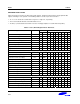
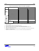
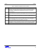
Table 9-1. S3F80J9 Port Configuration Overview (28-SOP)
Port Configuration Options
Port 0 8-bit general-purpose I/O port; Input or push-pull output; external interrupt input on falling edges,
rising edges, or both edges; all P0 pin circuits have noise filters and interrupt enable/disable
register (P0INT) and pending control register (P0PND); Pull-up resistors can be assigned to
individual P0 pins using P0PUR register settings. This port is dedicated for key input in IR
controller application.
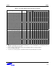
P1.0–P1.3 General-purpose I/O port; Input without or with pull-up, open-drain output, or push-pull output.
This port is dedicated for key output in IR controller application. After reset, init status is C-MOS
input.
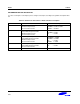
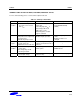
Port 2 8-bit general-purpose I/O port; Input or push-pull output. The P2 pins, P2.0–P2.7, can be used as
external interrupt inputs and have noise filters. The P2INT register is used to enable/disable
interrupts and P2PND bits can be polled by software for interrupt pending control. Pull-up resistors
can be assigned to individual P2 pins using P2PUR register settings.
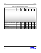
P3.0–P3.1 P3.0 is configured input functions (Input mode, with or without pull-up, for normal input or T0CAP)
or output functions (push-pull or open-drain output mode, for normal output or T0PWM). P3.1 is
configured input functions (Input mode, with or without pull-up, for normal input) or output
functions (push-pull or open-drain output mode, for normal output or REM function). P3.1 is
dedicated for IR drive pin and P3.0 can be used for indicator LED drive.
P3.7 P3.7 is not configured for I/O pin and it only used to control carrier signal on/off.