
User`s manual
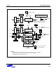

S3F80J9 BASIC TIMER and TIMER 0
10-11
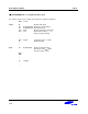
) PROGRAMMING TIP — Programming Timer 0
This sample program sets timer 0 to interval timer mode, sets the frequency of the oscillator clock, and
determines the execution sequence which follows a timer 0 interrupt. The program parameters are as follows:
— Timer 0 is used in interval mode; the timer interval is set to 4 milliseconds
— Oscillation frequency is 6 MHz
— General register 60H (page 0) → 60H + 61H + 62H + 63H + 64H (page 0) is executed after a timer 0 interrupt
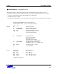
VECTOR 00FAH,T0OVER ; Timer 0 overflow interrupt
VECTOR 00FCH ,T0INT ; Timer 0 match/capture interrupt
ORG 0100H
RESET: DI ; Disable all interrupts
LD BTCON,#0AAH ; Disable the watchdog timer
LD CLKCON,#18H ; Select non-divided clock
CLR SYM ; Disable global and fast interrupts
CLR SPL ; Stack pointer low byte → "0"
; Stack area starts at 0FFH
•
•
•
LD T0CON,#4BH ; Write ‘00100101B’
; Input clock is f
OSC
/256
; Interval timer mode
; Enable the timer 0 interrupt
; Disable the timer 0 overflow interrupt
LD T0DATA,#5DH ; Set timer interval to 4 milliseconds
; (6 MHz/256) ÷ (93 + 1) = 0.25 kHz (4 ms)
SRP #0C0H ; Set register pointer → 0C0H
EI ; Enable interrupts
•
•
•
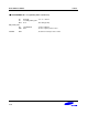
T0INT: PUSH RP0 ; Save RP0 to stack
SRP0 #60H ; RP0 ← 60H
INC R0 ; R0 ← R0 + 1
ADD R2,R0 ; R2 ← R2 + R0
ADC R3,R2 ; R3 ← R3 + R2 + Carry
ADC R4,R0 ; R4 ← R4 + R0 + Carry
(Continued on next page)