(AB68-00511B)SCC-B2391-01Eng 2005.6.
(AB68-00511B)SCC-B2391-01Eng 2005.6.17 3:44 PM ˘ ` 2 Important Safety Instructions CAUTION RISK OF ELECTRIC SHOCK DO NOT OPEN E CAUTION: TO REDUCE THE RISK OF ELECTRIC SHOCK, DO NOT REMOVE REAR COVER. NO USER SERVICEABLE PARTS INSIDE. REFER TO QUALIFIED SERVICE PERSONNEL. This symbol indicates high voltage is present inside. It is dangerous to make any kind of contact with any inside part of this product.
(AB68-00511B)SCC-B2391-01Eng 2005.6.17 3:44 PM ˘ 1. 2. 3. 4. 5. 6. 7. 8. 9. 10. 11. 12. 13. 14. ` 3 Read these instructions. Keep these instructions. Heed all warnings. Follow all instructions. Do not use this apparatus near water. Clean only with dry cloth. Do not block any ventilation openings. Install in accordance with the manufacturer’s instructions. Do not install near any heat sources such as radiators, heat registers, or other apparatus (including amplifiers) that produce heat.
(AB68-00511B)SCC-B2391-01Eng 2005.6.17 3:44 PM ˘ ` 4 Contents Chapter 1 Introduction ........................................................ 5 Chapter 2 Special Features ............................................. 6 Chapter 3 Installation ........................................................... 7 E Checking the contents of the package .............. 7 Precautions in Installation and Use ................... 8 Connecting Auto Iris Lens Connector ................ 9 Lens Fixing .................
(AB68-00511B)SCC-B2391-01Eng 2005.6.17 3:44 PM ˘ Chapter 1 ` 5 Introduction DAYNIGHT camera is a low brightness camera, which improves the sensitivity by operating with a color mode at the over of regular brightness and operated with a B/W mode by canceling the IR Cut function at the below of regular brightness. Also, it can be used linked with the separated infrared ray emission device.
(AB68-00511B)SCC-B2391-01Eng 2005.6.17 3:44 PM ˘ Chapter 2 ` 6 Special Features High Sensitivity It has an up-to-date 1/3" Super-HAD IT CCD for an image of high sensitivity. E Resolution It realizes high resolution resulting from full digital image processing supported by a state-of-art digital signal technology. Superior Back Light Adjustment Function In case the object has a bright illumination or sunlight behind it, this camera adjusts the image shaded by the back light for clear photographs.
(AB68-00511B)SCC-B2391-01Eng 2005.6.17 3:44 PM ˘ Chapter 3 ` 7 Installation This chapter describes what should be checked before installation, how to set the installation environment, and what should be done during installation. Then, it describes how to install the camera and connect the cable in actual circumstances. Checking the contents of the package Be sure to check if the following items are included in the package.
(AB68-00511B)SCC-B2391-01Eng 2005.6.17 3:44 PM ˘ ` 8 Precautions in Installation and Use E ① Do not attempt to disassemble the camera yourself. ➁ Be cautious in handling the camera. Avoid striking or shaking the camera. Be cautious to avoid damage on the camera caused by improper storage or operation. ➂ Do not expose this camera to rain or moisture. Do not operate this camera on a wet place. ➃ Do not use strong or abrasive detergents when cleaning the camera body. Use a dry cloth to clean the camera.
(AB68-00511B)SCC-B2391-01Eng 2005.6.17 3:44 PM ˘ ` 9 Connecting Auto Iris Lens Connector Prepare the following Auto Iris Lens Connector supplied with the camera. E Rb Pin3 Pin1 Pin4 Pin2 Connect the cable of the control cable, whose covering is stripped, to the Auto Iris Lens Connector as shown below. Pin No.
(AB68-00511B)SCC-B2391-01Eng 2005.6.17 3:44 PM ˘ Lens Fixing E In case of CS lenses Turn the CS lens clockwise until it is fixed as shown as follows. CS lens In case of C lenses Turn the C-mount adapter clockwise to fix it. Then turn the C lens clockwise until it is fixed as follows.
(AB68-00511B)SCC-B2391-01Eng 2005.6.17 3:44 PM ˘ ` 11 Setting Lens Selection Switch When lens mounting is completed, set the Lens selection Switch on the side of the camera according to the mounted lens type. When the mounted lens is an Auto Iris Lens of the DC control type, set the Lens Selection Switch to "DC". When the mounted lens is an Auto Iris Lens of the Video control type, set the Lens Selection Switch to "VIDEO".
(AB68-00511B)SCC-B2391-01Eng 2005.6.17 3:44 PM ˘ E ` 12 Lenses with zoom function ① Image an object with high resolution(letticed) at a distance of 3 to 5 m and zoom in the lens as close to TELE as possible. Then adjust the lens focus bar until the object is seen best. ➁ Zoom in the lens as close to WIDE as possible and adjust the BACK FOCUS adjustment bar until the object is seen best.
(AB68-00511B)SCC-B2391-01Eng 2005.6.17 3:44 PM ˘ ` 13 Connecting Cables and Checking Operation 1 First, connect the connector of the BNC cable to the Video Out terminal 2 Second, connect the other connector of the BNC cable to the Video In terminal.
(AB68-00511B)SCC-B2391-01Eng 2005.6.17 3:44 PM ˘ E ` 14 3 Third, connect the power cable. ① AC24V/DC12V Power Input Camera. Connect 2 lines of the power adapter using a screwdriver to the power IN Terminal of the camera as shown below. ❉ Without the distinction of the polarity, connect to the AC24V or DC12V power source. ➁ AC230V Power Input Camera Connect the power input cord to the AC230V power source.
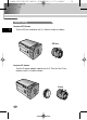
(AB68-00511B)SCC-B2391-01Eng 2005.6.17 3:44 PM ˘ ` 15 Chapter 4 Part Names and Functions Side View ➂ Auto Iris Lens Connector ① Mount Adapter Fixing Groove E ➅ Back Focus Control Bar ⑤ ALC Lens Selection Switch ➃ Auto Iris Lens Control Cable ➁ Camera Lens ① Mount Adapter Fixing Groove This groove is used for screwing the mount adapter, a part of the bracket where the camera will be installed. ➁ Camera Lens(Option) This lens is installed in the camera.
(AB68-00511B)SCC-B2391-01Eng 2005.6.
(AB68-00511B)SCC-B2391-01Eng 2005.6.17 3:44 PM ˘ ` 17 ① Power connection port AC24V/DC12V Camera : It is a port connected to the power adaptor cable. AC230V Camera : It is Power cord. E ➁ POWER LED If the power of a camera is supplied normally, the LED is ON. ➂ ➃ INC and DEC Switch Both switches increase or decrease the profit of RED and BLUE to fix a color temperature as you wish while AWB among the FUNCTION switches is off(USER) and control the vertical synchronous phase while both AWB and L/L are on.
(AB68-00511B)SCC-B2391-01Eng 2005.6.17 3:44 PM ˘ E ` 18 1) SW1(L/L) : Set to OFF, the camera activates the internal synchronization mode and set to ON, the power synchronization mode. If you connect multi cameras to the sequential switcher to enter the automatic conversion mode, the screen will bounce every screen while the camera stays in INT(internal synchronization).
(AB68-00511B)SCC-B2391-01Eng 2005.6.17 3:44 PM ˘ ` 19 ➅ DC IRIS Level Controller When the ALC lens selection switch is set to DC, use the same control bar as the driver to control the IRIS level. E ⑦ Video Output Port This port shall be connected to the monitor video input port or equivalent. You may output camera video signals through this port. ⑧ DAYNIGHT Selection Switch If you set this switch to AUTO, the DAYNIGHT function will be automatically activated according to the illumination.
(AB68-00511B)SCC-B2391-01Eng 2005.6.17 3:44 PM ˘ Product Specification SCC-B2391P/B2091P ITEM E Product Type Contents CCTV Camera Broadcasting System PAL STANDARD SYSTEM CCD 1/3 Super-HAD CCD Effective Pixels 752(H) x 582(V) Scanning Type 625 Line, 2:1 Interlace INTERNAL : 15,625Hz(H) 50 Hz(V) Frequency LINE LOCK : 15,625Hz(H) 50 Hz(V) INTERNAL Sync Type LINE LOCK(When AC Power source is used) Resolution(H) 540(Color)/570(B/W) TV Lines S/N Ratio About 50dB Minimum Illumination 0.
(AB68-00511B)SCC-B2391-01Eng 2005.6.17 3:44 PM ˘ ITEM ` 21 Contents E ALC DC IRIS LENS ALC/ELC VIDEO LENS ELC Electronic Shutter Iris Function (Max. 1/100 Ksec) Color Temperature AWB/MANUAL BLC ON AGC ON Video Output COMPOSITE VIDEO OUT 1V p_p 75Ω/BNC Power Source B2391P : AC24V±10%(50Hz±0.3Hz), DC12V+10%~-5% B2091P : AC220V~AC240V(50Hz±0.3Hz) Power Consumption B2391P : About 3W B2091P : About 4W Operating Temp -10°C~+50°C Operating Humidity ~90% Size 68(W)x55(H)x128.
(AB68-00511B)SCC-B2391-01Eng 2005.6.17 3:44 PM ˘ Product Specification SCC-B2391/B2300 ITEM E Product Type Contents CCTV Camera Broadcasting System NTSC STANDARD SYSTEM CCD 1/3 Super-HAD CCD Effective Pixels B2391 : 768(H) x 494(V) B2300 : 510(H) x 492(V) Scanning Type 525 Line, 2:1 Interlace INTERNAL : 15,734Hz(H) 59.
(AB68-00511B)SCC-B2391-01Eng 2005.6.17 3:44 PM ˘ ITEM ` 23 Contents E ALC DC IRIS LENS ALC/ELC VIDEO LENS ELC Electronic Shutter Iris Function (Max. 1/100 Ksec) Color Temperature AWB/MANUAL BLC ON AGC ON Video Output COMPOSITE VIDEO OUT 1V p_p 75Ω/BNC Power Source AC24V ±10%(60Hz±0.3Hz), DC12V+10%~-5% Power Consumption About 3Watts Operating Temp -10°C~+50°C Operating Humidity ~90% Size 68(W)x55(H)x128.
(AB68-00511B)SCC-B2391-01Eng 2005.6.17 3:44 PM ˘ ` 24 Correct Disposal of This Product (Waste Electrical & Electronic Equipment) (Applicable in the European Union and other European countries with separate collection systems) This marking shown on the product or its literature, indicates that it should not be disposed with other household wastes at the end of its working life.
(AB68-00511B)SCC-B2391-06Pl 2005.6.
(AB68-00511B)SCC-B2391-06Pl 2005.6.17 3:31 PM ˘ ` 112 Important Safety Instructions OSTRO˚NIE! NIE OTWIERAå - GROZI PORA˚ENIEM PRÑDEM Pl OSTRO˚NIE: ABY ZMNIEJSZYå RYZYKO PORA˚ENIA PRÑDEM NIE NALE˚Y ZDEJMOWAå TYLNEJ CZ¢ÂCI OBUDOWY. BRAK TAM CZ¢ÂCI DO SAMODZIELNEJ NAPRAWY PRZEZ U˚YTKOWNIKA. ZG¸O USZKODZENIE DO WYKWALIFIKOWANEGO PUNKTU SERWISU. Symbol ten ostrzega przed wysokim napi´ciem wewnàtrz. Niebezpieczny jest kontakt z jakimikolwiek elementami wewnàtrz urzàdzenia.
(AB68-00511B)SCC-B2391-06Pl 2005.6.17 3:31 PM ˘ 1. 2. 3. 4. 5. 6. 7. 8. 9. 10. 11. 12. 13. 14. ` 113 Zapoznaj si´ z instrukcjami. Zachowaj instrukcje obs∏ugi. Zwracaj uwag´ na wszystkie ostrze˝enia. Post´puj zgodnie z instrukcjami. Nie u˝ywaj tego urzàdzenia w pobli˝u wody. CzyÊç jedynie suchà szmatkà. Nie blokuj wejÊç wentylacyjnych. Dokonaj instalacji zgodnie ze wskazówkami proucenta.
(AB68-00511B)SCC-B2391-06Pl 2005.6.17 3:31 PM ˘ ` 114 Spis treÊci Rozdzia∏ 1 Wprowadzenie.......................................................5 Rozdzia∏ 2 Charakterystyka.....................................................6 Rozdzia∏ 3 Instalacja ................................................................7 Sprawdzanie zawartoÊci opakowania ..................7 Ârodki ostro˝noÊci podczas instalacji i u˝ytkowania ...........................................................
(AB68-00511B)SCC-B2391-06Pl 2005.6.17 3:31 PM ˘ ` 115 Rozdzia∏ 1 Wprowadzenie Kamera DAYNIGHT(Dzieƒ/noc) jest kamerà o niskiej jasnoÊci, co powoduje zwi´kszenie czu∏oÊci przy funkcjonowaniu w trybie kolorów w jasnoÊci powy˝ej przeci´tnej jasnoÊci zaÊ w trybie B/W po anulowaniu funkcji IR Cut poni˝ej regularnej jasnoÊci. Mo˝e byç równie˝ stosowana w po∏àczeniu z oddzielnym urzàdzeniem emitujàcym promieniowanie podczerwieni.
(AB68-00511B)SCC-B2391-06Pl 2005.6.17 3:31 PM ˘ ` 116 Rozdzia∏ 2 Charakterystyka Wysoka czu∏oÊç Dla obrazu o wysokiej czu∏oÊci posiada nowoczesny 1/3" Super-HAD IT CCD . RozdzielczoÊç Wysoka rozdzielczoÊç zapewniona jest dzi´ki pe∏nemu cyfrowemu przetwarzaniu obrazu w po∏àczeniu z doskona∏à technologià sygna∏u cyfrowego.
(AB68-00511B)SCC-B2391-06Pl 2005.6.17 3:31 PM ˘ ` 117 Rozdzia∏ 3 Instalacja Rozdzia∏ ten opisuje co nale˝y sprawdziç przed zainstalowaniem, w jaki sposób przygotowaç otoczenie instalowanego urzàdzenia i w jaki sposób nale˝y je zainstalowaç. Nast´pnie opisany zosta∏ sposób instalacji kamery oraz po∏àczenia przewodów w danych warunkach. Sprawdzanie zawartoÊci opakowania Sprawdê, czy nast´pujàce elementy znajdujà si´ w opakowaniu.
(AB68-00511B)SCC-B2391-06Pl 2005.6.17 3:31 PM ˘ ` 118 Ârodki ostro˝noÊci podczas instalacji i u˝ytkowania ① Nie rozmontowuj kamery samodzielnie ➁ Ostro˝nie obchodê si´ z kamerà. Unikaj wstrzàsów lub uderzeƒ. Przechowuj i pos∏uguj si´ kamerà we w∏aÊciwy sposób, by uniknàç jej uszkodzenia. ➂ Nie wystawiaj kamery na dzia∏anie deszczu lub wilgoci. Nie u˝ywaj kamery w mokrych miejscach. Pl ➃ Podczas czyszczenia unikaj silnie dzia∏ajàcych Êrodków. Kamer´ nale˝y przecieraç suchà szmatkà.
(AB68-00511B)SCC-B2391-06Pl 2005.6.17 3:31 PM ˘ ` 119 Pod∏àczanie z∏àcza obiektywu z automatycznà przes∏onà Przygotuj do∏àczone do kamery z∏àcze obiektywu z automatycznà przes∏onà. Rb Pin3 Pin1 Pin4 Pl Pin2 Pod∏àcz przewód obs∏ugi z os∏onà w paski do z∏àcza obiektywu z automatycznà przes∏onà.
(AB68-00511B)SCC-B2391-06Pl 2005.6.17 3:31 PM ˘ ` 120 Mocowanie obiektywu Dla obiektywów CS Przekr´caj obiektyw CS zgodnie z kierunkiem ruchu wskazówek zegara dopóki nie zostanie zamocowany jak na obrazku. Obiektyw CS Pl Dla obiektywów C Przekr´caj z∏àcze do monta˝u C zgodnie z ruchem wskazówek zegara, by go zamocowaç. Nast´pnie przekr´ç obiektyw C zgodnie z ruchem wskazówek zegara w celu jego zamocowania.
(AB68-00511B)SCC-B2391-06Pl 2005.6.17 3:31 PM ˘ ` 121 Ustawienia w∏àcznika wyboru obiektywu Po zamontowaniu obiektywu ustaw przycisk wyboru obiektywu z boku kamery zgodnie z rodzajem zamontowanego obiektywu. W przypadku zamontowania obiektywu z automatycznà przes∏onà dzia∏ajàcego pod zasilaniem DC, ustaw prze∏àcznik wyboru obiektywu w pozycji “DC”. Je˝eli zamontowany obiektyw to obiektyw z automatycznà przes∏onà typu video, ustaw prze∏àcznik wyboru obiektywu na “VIDEO”.
(AB68-00511B)SCC-B2391-06Pl 2005.6.17 3:31 PM ˘ ` 122 Obiektywy z funkcjà zoom ① Obejmij obiekt o du˝ej rozdzielczoÊci w dystwnsie 3-5 m i przybli˝ zoom obiektywu najbli˝ej TELE jak to mo˝liwe. Nast´pnie reguluj ostroÊç obiektywu by ustawiç go w najlepszej widocznoÊçi. ➁ Przybli˝ zoom w oobiektywie najbli˝ej jak to mo˝liwe do WIDE i reguluj BACK FOCUS a˝ do uzyskania najlepszej widocznoÊci obiektu.
(AB68-00511B)SCC-B2391-06Pl 2005.6.17 3:31 PM ˘ ` 123 Pod∏àczanie przewodów I sprawdzania funkcjonowania 1 Po∏àcz z∏àcze przewodu BNC do terminaly Video In. 2 Pod∏àcz inne z∏àcza kabla BNC do terminalu Video In.
(AB68-00511B)SCC-B2391-06Pl 2005.6.17 3:31 PM ˘ ` 124 3 Pod∏àcz przewód zasilania ① Kamera o zasilaniu AC24V/DC12V Pod∏àcz dwie linie zasilacza za pomocà Êrubokr´tu z terminalem IN kamery, jak na rysunku poni˝ej. ❉ Bez polaryzacji po∏àcz do êród∏a zasilania AC24V lub DC12V Pl ➁ Kamera o zasilaniu AC230V Po∏àcz przewód zasilania do êród∏a zasilania AC230V.
(AB68-00511B)SCC-B2391-06Pl 2005.6.17 3:31 PM ˘ ` 125 Rozdzia∏ 4 Nazwy i funkcje cz´Êci Widok z boku ① Mocowanie zasilania Wy˝∏obienie ➂ ¸àcznik obiektywu Auto Iris ➅ Ognisko z ty∏u Kontrolka ⑤ ALC prze∏àcznik wyboru obiektywu Pl ➃ Przewód zasilanie obiektywu z automatycznà przes∏onà ➁ Obiektyw kamery ① Mocowanie zasilania Wy˝∏obienie Wy˝∏obienie to wykorzystywane jest w celu przykr´cenia z∏àcznika, tego elementu gdzie kamera b´dzie zainstalowana.
(AB68-00511B)SCC-B2391-06Pl 2005.6.
(AB68-00511B)SCC-B2391-06Pl 2005.6.17 3:31 PM ˘ ` 127 ① Port zasilania Kamera AC24V/DC12V: Jest to port po∏àczony do przewodu zasilania. Kamera AC230V: Przewód zasilania. ➁ Dioda zasilania JeÊli zasilanie kamery odbywa si´ bez zak∏óceƒ dioda jest w pozycji ON(w∏àczonej).
(AB68-00511B)SCC-B2391-06Pl 2005.6.17 3:31 PM ˘ ` 128 1) SW1(L/L) : W pozycji OFF kamera aktywuje tryb synchronizacji wewn´trznej, w pozycji ON tryb synchronizacji mocy. Pod∏àczanie kilku kamer do prze∏àcznika sekwencyjnego w celu wejÊcia w tryb automatycznej konwersji, ekran poka˝e ka˝dy z obrazów, gdy kamera pozostanie w trybie INT (synchronizacja wewn´trzna).
(AB68-00511B)SCC-B2391-06Pl 2005.6.17 3:31 PM ˘ ` 129 ➅ Kontrola poziomu DC IRIS (migawki zasilanej pràdem) Kiedy prze∏àcznik wyboru obiektywu ALC ustawiony jest w pozycji DC, u˝ywaj tego samego sterownika jak driver, w celu obs∏ugiwania poziomu IRIS. ⑦ Port wyjÊcia video Port ten powinien zostaç po∏àczony z portem wejÊcia video monitora lubjego ekwiwalentem. Port ten s∏u˝y do wyjÊcia sygna∏ów kamery.
(AB68-00511B)SCC-B2391-06Pl 2005.6.
(AB68-00511B)SCC-B2391-06Pl 2005.6.17 3:31 PM ˘ POZYCJA ` 131 OPIS ALC/ELC ALC OBIEKTYW DC IRIS(migawka zasilana pràdem) OBIEKTYW VIDEO ELC Funkcja elektronicznej migawki obiektywu (Max. 1/100 Ksek) Temperatura koloru AWB/R¢CZNY BLC W¸ (Kompensacja oÊwietlenia t∏a) AGC W¸ WyjÊcie video Z¸O˚ONE WYJÂCIE VIDEO Pl 1V p_p 75Ω/BNC èród∏o zasilania Zu˝cie energii B2391P : AC24V±10%(50Hz±0.3Hz), DC12V+10%~-5% B2091P : AC220V~AC240V(50Hz±0.
(AB68-00511B)SCC-B2391-06Pl 2005.6.17 3:31 PM ˘ ` 132 Dane techniczne SCC-B2391/B2300 POZYCJA OPIS Typ produktu Kamera CCTV System nadawania SYSTEM NTSC STANDARD CCD 1/3”IT Metoda CCD Pixele efektywne B2391 : 768(H)x494(V) B2300 : 510(H)x492(V) Typ skanowania Pl 525 linii, 2:1 Interlace WEWN¢TRZNE : 15,734Hz(H) 59.
(AB68-00511B)SCC-B2391-06Pl 2005.6.17 3:31 PM ˘ POZYCJA ` 133 OPIS ALC/ELC ALC OBIEKTYW DC IRIS(migawka zasilana pràdem) OBIEKTYW VIDEO ELC Funkcja elektronicznej migawki obiektywu (Max. 1/100 Ksek) Temperatura koloru AWB/R¢CZNY BLC W¸ (Kompensacja oÊwietlenia t∏a) AGC W¸ WyjÊcie video Z¸O˚ONE WYJÂCIE VIDEO Pl 1V p_p 75Ω/BNC èród∏o zasilania AC24V ±10%(60Hz±0.
(AB68-00511B)SCC-B2391-06Pl 2005.6.17 3:31 PM ˘ ` 134 Prawid∏owe usuwanie produktu (zu˝yty sprz´t elektryczny i elektroniczny) Oznaczenie umieszczone na produkcie lub w odnoszàcych si´ do niego tekstach wskazuje, ˝e produktu po up∏ywie okresu u˝ytkowania nie nale˝y usuwaç z innymi odpadami pochodzàcymi z gospodarstw domowych.