DIGITAL LASER MFP SCX-5315F Series SCX-5315F SCX-5115 SERVICE MANUAL CONTENTS DIGITAL LASER MFP 1. Precautions 2. Specifications 3. Disassembly 4. Troubleshooting 5. Exploded Views and Parts List 6. Block Diagram 7.
Specification 2. Specification Specifications are correct at the time of printing. Product specifications are subject to change without notice. See below for product specifications.
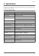
Specification 2-2 Printer Specifications Item Description Printing Method Laser Scanning Unit + Electro Photography *Speed Single Side : Up to 15 PPM (Letter Size, 5% Character Pattern) Duplex : Up to 7.
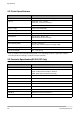
Specification 2-4 Scanner Specification Item Description Type Flatbed(with ADF) *Speed Mono : Up to 1.2 msec/line, Color : Up to 2.5 msec/line Device Color CCD(Charge Coupled Device) Module Interface IEEE1284(ECP Support) USB(without HUB Mode) Compatibility TWAIN Standard , WIA Optical Resolution(H X V) Up to 600 x 600 DPI effective output Interpolation Resolution Max. 4800 dpi Halftone 256 Levels Effective Scan width 8.
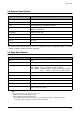
Specification 2-6 Telephone Specification(SCX-5315F Only) Item Description Speed Dial 80EA Tone/Pulse Tone only user modeTone/Pulse selectable in tech mode.
TIDI This Service Manual is a property of Samsung Electronics Co.,Ltd. Any unauthorized use of Manual can be punished under applicable International and/or domestic law. This service manual is also provided on the web, the ITSELF system Samsung Electronics Co., Ltd. “http://itself.sec.samsung.co.kr” © Samsung Electronics Co.,Ltd. JULY 2003 Printed in Korea. VERSION NO. : 1.
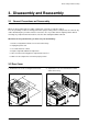
Disassembly and Reassembly 3. Disassembly and Reassembly 3-1 General Precautions on Disassembly When you disassemble and reassemble components, you must use extreme caution. The close proximity of cables to moving parts makes proper routing a must. If components are removed, any cables disturbed by the procedure must be restored as close as possible to their original positions. Before removing any component from the machine, note the cable routing that will be affected.
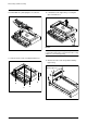
Disassembly and Reassembly 3-3 Scanner Ass'y 1. Before you remove the Scanner Ass'y, you should remove: - Rear Cover (see page 3-1) 4. Open the Side Cover assembly first to open the Front cover. In the other words, close the front cover first to assembly it. 2. Take out the Shield Main Upper.Unplug the one connector and CCD cable. Side Cover Ass’y 2 1 Front Cover Notice : 5. Remove two screws. To avoid damage to the CCD cable connector ensure that you pull the cable out carefully.
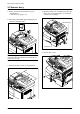
Disassembly and Reassembly 6. Pull up the Scanner Ass'y in the direction of arrow. 8. Open the ADF Ass’y in the direction of arrow. Pull the ADF Ass'y upward and remove it. 9. Remove the three screws securing the Platen Ass'y. 7. Remove the connector from the Platen Ass'y.
Disassembly and Reassembly 10. Pull the OPE Ass'y and unplug the one connector. 12. Unlatch the Scan Upper Ass'y securing the glass and remove it. Notice : When dismantling the Scan Assy ensure your work area is clean. Dirt or dust on the scan head can lead to a degradation in scanned image quality. 11. Remove the five screws securing the Platen Ass'y. 13. Remove the two scews and pull the Dummy Upper Ass’y.
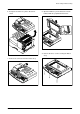
Disassembly and Reassembly 14. Remove the four screws and Channel Base Frame. 16. Remove the CCD cable. CCD Cable Channel Base Frame 15. Remove the five screws and Dummy ScanLower. 17. Pull up the Shaft CCD and take out the Scanner Module. Shaft CCD Pully Scanner Module Cover Dummy Lower Cover Scan Lower Samsung Electronics Belt 18. Remove three screws and take out the Motor Bracket.
Disassembly and Reassembly 19. Remove the OPE Harness from the Platen PBA. Remove two screws and take out the Platen PBA. Platen PBA OPE Harness Notice : Take special care when reassembling the CCD Module onto the Platen Ass'y. The CCD Module is located just to the right side the Belt Tension Spring as shown below.
Disassembly and Reassembly 3-4 ADF Ass'y 1. Before you remove the ADF Ass'y, you should remove: - Rear Cover (see page 3-1) - Scanner Ass'y (see page 3-2) 4. Pull the ADF Ass'y upward and remove it. 2. Remove the five screws from the Platen Cover. Platen Cover Ass’y Platen Cover Ass’y 5. Tack out he Open Cover. 3. Open the Cover. Remove Cover Side R. Unlatch the Side Cover L by pushing the catch hooked to the Platen Cover using a sharp tool and remove Side Cover L.
Disassembly and Reassembly 6. Take out the Pick-up Ass’y. Remove the four screws and the ADF Upper. 7. Remove three screws and take out the ADF Motor ass'y.
Disassembly and Reassembly 3-5 OPE Ass'y 1. Before you remove the OPE Ass'y, you should remove: - Rear Cover (see page 3-1) - Scanner Ass'y (see page 3-2) 4. Remove the key pad from the unit. 2. Remove ten screws securing the OPE PBA and the LCD Module from the OPE Cover. Caution The above information is for the SCX-5315F model. For the SCX-5115 model, the OPE Ass’y is slightly different, prats maked “a” are not fitted. 3. Remove the contact rubbers from the unit.
Disassembly and Reassembly 3-6 Side Cover Ass'y 1. Remove the two screws to release the Stopper(Main Frame side) securing the Side Cover to the Main Frame. * MP-Tray 1. To dismantle the MP tray release the lower hinges (1). 1 1 2. Completely open the Side Cover door. The left hand hinge (1) should be lifted to free it. Then push the whole door assembly to the left to free the right hand hinge (2). 2. As shown in (1) below align the door supports in a horizontal position.
Disassembly and Reassembly * Duplex Ass’y * Transfer Roller Ass’y 1. To remove the Duplex Ass'y from the Side Door Ass' locate the plastic clips, 2 on each side, and release them. 1. Take out the Transfer Roller, as shown below.
Disassembly and Reassembly 3-7 Fuser Ass'y 1. Before you remove the Fuser Ass'y, you should ensure power is off and remove : - Rear Cover Ass'y (see page 3-1) - Side Cover Ass'y (see page 3-9) 4. Remove the three screws and take out the Fuser Ass'y. 2. Remove the two screws and take out the Connector Cover and the Cover Bracket. Cover Bracket 5. Remove the four screws and take out the Thermostat. 3. Unplug the one connector.
Disassembly and Reassembly 6. Remove the two screws and take out the Halogen Lamp. 7. Remove 2 screws and hinge open the Lower Fuser Ass'y, remove the Heat Roller Ass'y from the Upper Fuser Ass'y.
Disassembly and Reassembly 3-8 Exit Ass'y 1. Before you remove Exit Ass'y, you should remove: - Rear Cover (see page 3-1) - Scanner Ass'y (see page 3-2) 3. Move the Exit Roller Release Lever to the upright position as shown in the diagram below and lift the exit ass'y to remove it. 2. Remove four screws, and then untie the harness from the Exit Upper. Unplug four connectors and unlatch the Dummy Base Frame, as shown below. 3-9 Cover Paper Exit Ass'y 1.
Disassembly and Reassembly 3-10 Drive Ass'y 1. Before you remove the Drive Ass'y, you should remove: - Rear Cover (see page 3-1) - Shield Main Upper (see page 3-2) 4. Remove the five screws and take out the Drive Ass'y. 2. Unplug the two connectors. (Main Motor:9pin, Duplex Solenoid : 2pin) Drive Ass’y 3. Remove the one screw and take out the Fan and Dust Fan.
Troubleshooting 4. Maintenance & Troubleshooting This chapter covers product maintenance, problem diagnosis and troubleshooting. It includes instructions for diagnosing and resolving print quality problems. This service manual covers both the SCX5315F and SCX5115 models. SCX5115 has printer, copier and scanner functions. The SCX5315F has all of the features of the SCX5115 and in addition has Fax capabilities.
Troubleshooting 4-2 Error Messages Error Message Description Solution RETRY REDIAL? The machine is waiting for the programmed interval to automatically redial. You can press START to immediately redial, or STOP to cancel the redial operation. COMM. ERROR A problem with FAX communications has occurred. Try again. DOCUMENT JAM Loaded document has Jammed in the scanner document feeder Clear the document Jam.
Troubleshooting Error Message Description Solution DRUM WARNING A warning that the OPC drum has almost reached the end of its life (14,000 Sides) You have 1000 pages of print life left in the OPC Drum. Continue to use, order a new OPC drum. REPLACE DRUM OPC drum is now life-expired (15,000 sides) Replace the OPC Drum Cartridge. NO CARTRIDGE When the machine detects that the toner cartridge has not been installed. Install the Cartridge.
Troubleshooting 4-3 User Mode The table below shows the settings and functions available in the User Mode. These are described in the user Guide. The table is given here to indicate possible settings that the user may have changed. 4-3-1 SCX-5315F ✳❑n❄❏❊on SYSTEM DATA SYSTEM ID ✶❏❆m CASSETTE PAPER ✰on❏❆n❏ LETTER / A4 / LEGAL BYPASS PAPER LETTER / A4 / LEGAL MESSAGE CONF.
Troubleshooting ✳❑n❄❏❊on MAINTENANCE ✶❏❆m ✰on❏❆n❏ CLEAN DRUM NEW DRUM NOTIFY TONER LOW ON / OFF TX CONFIRM SCHEDULE JOB PHONE BOOK SYSTEM LIST TX JOURNAL RX JOURNAL HELP LIST HELP LIST 4-3-2 SCX-5115 ✳❑n❄❏❊on SYSTEM DATA ✶❏❆m CASSETTE PAPER ✰on❏❆n❏ LETTER / A4 / LEGAL BYPASS PAPER LETTER / A4 / LEGAL POWER SAVE ON / OFF SELECT LANGUAGE ENG/GER/FRE/ITA/SPA/POR/DUT USB MODE FAST / SLOW HELP LIST HELP LIST PRINTOUT MAINTENANCE CLEAN DRUM NEW DRUM REPORTS SYSTEM DATA HELP LIST HELP LIS
Troubleshooting 4-4-2 Setting-up System in Tech Mode 4-4-2-1 SCX-5315F(SETUP : #, 1, 9, 3, 4) ✳❑n❄❏❊on SYSTEM DATA ✶❏❆m DIAL MODE ✰on❏❆n❏ TONE / PULSE MODEM SPEED ERROR RATE 5% /10% SET TX LEVEL 09-15 SILENCE TIME 12 / NU / OFF SYSTEM ID The same as User Mode DATE & TIME The same as User Mode SYSTEM SETUP The same as User Mode MEMORY CLEAR CLEAR ALL MEMORY DELAY TX The same as User Mode MEMORY TX The same as User Mode PRIORITY TX The same as User Mode POLLING The same as User Mode
Troubleshooting ✳❑n❄❏❊on REPORTS ✶❏❆m MSG.
Troubleshooting 4-4-3 SYSTEM DATA DIALING MODE Select the dialing mode according to the user's line status. TONE: Electrical type of dial PULSE: Mechanical type of dial SILENCE TIME In ANS/FAX mode, after a call is picked up by the answering machine, the machine monitors the line. If a period of silence is detected on the line at any time, the call will be treated as a fax message and the machine begins receiving. Silence detection time is selectable between limited (about 12 seconds) and unlimited time.
Troubleshooting 4-4-5 MAINTENANCE CLEAN DRUM Use this feature to remove toner particles remaining in the OPC drum unit. Use this feature when print quality falls or when marks or specks appear on the printout. You should perform this feature several times until a clean printout appears. The machine automatically pulls in a sheet of paper and prints out. Excess toner particles on the OPC drum surface are fixed to the paper. FLASH UPGRADE This function is used to update the system Firmware.
Troubleshooting CLEAR COUNT This function erases the counters stored in system memory. These are shown in the highlighted area in the Sytem data List shown below (printed in TECH MODE) Note the Current Drum Page Count cannot be erased.
Troubleshooting NOTIFY TONER LOW With this feature enabled, when the toner becomes low, the toner low information will be sent to a specified contact point, for example, the service company. After you access this menu, select ON, and when the LCDprompts, enter the name and the number of the contact point, the customer's fax number, the model name, and the serial number.
Troubleshooting RECEPTION This journal shows information relating to document reception, the time and dates of up to 40 of the most recent documents received are stored. TRANSMISSION This journal shows information relating to document transmission, the time and dates of up to 40 of the most recent documents transmitted are stored. SYSTEM DATA This list provides a list of the user system data settings and tech mode settings. PHONEBOOK It lists all telephone numbers that have been stored in the machine.
Troubleshooting DOS Command mode This method is just for Parallel Port. Connect to PC with Parallel cable and enter DOS Command to upgrade the Firmware. < Method > a). You will need the following files:- down.bat, down_com.bin, fprt.exe, and “Rom File”: this is the firmware file to be loaded into the printer. Save the files in the same folder, close to the root of C;, e.g. C\TEMP b). At a DOS prompt, input one of the commands shown below and press the enter key.
Troubleshooting 4-5 ENGINE TEST MODE The Engine Tests Mode provides useful test functions for checking the status of the print engine. It can test many of the separate sections of the print engine and displays the result of the test on the LCD. These tests are classified in 6 groups (0~5), and the functions of these tests are shown below. 4-5-1 To enter the Engine Test Mode Press MENU, #, 1, 9, 3, 1 in sequence, and the LCD briefly displays ‘Engine Test Mode’, the machine has entered service (tech) mode.
Troubleshooting 4-6 Troubleshooting 4-6-1 Scanner 4-6-1-1 COPY PROBLEM White copy Black copy Defective image quality Abnormal noise Samsung Electronics ITEMS TO BE CHECKED. HOW TO SOLVE • Ensure the Scanner cover is closed. • Room lighting can penetrate thin paper causing quality problems • Check shading profile • Carry out the “Adjust Shading” procedure in Tech mode • Check the CCD problem in Main PBA. • Check the CCD harness contact. • Check shading profile.
Troubleshooting 4-6-1-2 PC-Scan PROBLEM Scanning Error Defective image Quality Abnormal noise 4-16 ITEMS TO BE CHECKED. HOW TO SOLVE • Check the printer cable is correctly installed. • Use standard IEEE1284 cable. • Check that the TWAIN driver is installed. • Remove any other scanner driver. • Reboot after reinstallation of the TWAIN driver. • Check the printer port (Parallel) BIOS settings. • Check the parallel-port-related items in the CMOS Setup. As a printer port, ensure ECP is selected.
Troubleshooting 4-6-2 FAX(only SCX-5315F) 4-6-2-1 FAX/TELEPHONE Precautions PROBLEM TEL LINE CANNOT BE ENGAGED (NO DIAL TONE) ITEMS TO BE CHECKED. • When you press “ OHD” key: a) Check line cord connection. b) Check MAIN LIU harness, and CN1 (LIU PBA). c )Check relay operation of LIU PBA : Is the control signal of CN18(main) low? HOW TO SOLVE a) insert it correctly into the connection jack called “line”. b) Replace defective parts. c) Replace main PBA IF the control signal of CN18(main) is high.
Troubleshooting 4-6-3 Print Quality Error Status Vertical black line and band Check Solution 1. Faulty Toner cartridge 2. LSU 3. Bad cleaning blade of drum cartridge. 1. Change Toner cartridge 2. Replace LSU 3. Chang Drum cartridge. 1. LSU window contamination 2. Toner cartridge 1. Clean LSU window 2. If not LSU, change Toner cartridge. 1. OPC is properly grounded? 2. LSU running well? 3. Bias voltage is correct? 4. Toner low? 5. Is there video data from Main PBA 1.
Troubleshooting Error Status Background Check Solution 1. High voltage output is normal? 2. C/R of Toner cartridge is contaminated? 1. Change the HVPS Board. 2. Print a number of “Cleaning” sheets – if problem persists change the cartridge.. 1. High voltage output. 2. Pre-Transfer Lamp. 3. Bad high voltage contact. 1. Change the HVPS Board. 2. Check PTL lamp comes on –replace if necessary 3. Clean the inside machine or replace toner cartridge. Stains on back of paper 1.
Troubleshooting Error Status Check Solution Different image density (left and right) 1. Uneven pressure between Charge roller and OPC Drum 2. Uneven pressure between Dev roller and OPC drum 3. Transfer roller’s pressure force uneven at each side 1. Change OPC cartridge 2. Change toner and / or OPC Drum 3. Check left and right transfer roller springs Horizontal lines or bands 1. Bad contact on high voltage terminal 2. Contamination of charge roller 3. Contamination of heat roller 4.
Troubleshooting No Image Digital Printer Digital Printer Digital Printer Digital Printer Digital Printer No image? A on next page NO YES Self test pattern prints? YES Check connection to computer or replace controller NO Self testing is possible ? NO Retest after replacing the connector or controller board YES Take out the cartridge and prepare the tester for electronic connection Is the OPC terminal of machine is well-connected to Frame? NO Repair or replace the GND terminal YES Does the v
Troubleshooting A Transfer voltage OK? (on the transfer roller shaft) NO YES Are the connection terminal and connection correct? NO Repair or replace terminal YES Replace HVPS or repair defective component Developing (-440V) and supplying (-590V) voltage are OK? NO Is the connection terminal OK? NO Repair or replace terminal YES YES Replace HVPS or repair defective component Does the counter indicate over the toner's guaranty life YES NO Transfer roller might be out of its location -> Locat
Troubleshooting All Black Digital Printer Digital Printer Digital Printer Digital Printer Digital Printer All black in printing area? NO YES Does the video data line to LSU transit to High/Low when printing? NO YES Check the path among video controller, engine board, HVPS, LSU for the shortage or open -> Repair or replace the boards Replace LSU Is charge voltage supplied from HVPS? NO Repair or replace HVPS YES Is the Hsync/ signal received in LSU? NO Replace LSU YES Charge part's contact
Troubleshooting Vertical White Line (Band) Digital Printer Digital Printer Digital Printer Digital Printer Digital Printer White line missing definitely? YES Dirt of dust stuck onto the window of internal lens of LSU -> Clean it or replace LSU Preventive obstacles through the path between OPC of developer and LSU prevent the path -> Remove the obstacles 4-24 NO Check if the printout is still has the same problem even right after passed through the transfer roller NO YES The ribs in fuser or toner
Troubleshooting Dark Image Digital Printer Digital Printer Digital Printer Digital Printer Digital Printer NO Dark selected via RCP? YES Change to Normal and test NO Same at Normal? END YES Works cor with -300V of Bias voltage? NO Repair or replace the defective component YES Works correctly after replaced LSU? NO Toner over supply due to the adjustment fault of metering blade in developer -> Replace developer YES The power of LSU is set high or internal problem -> Replace LSU or adjust volu
Troubleshooting Background Digital Printer Digital Printer Digital Printer Digital Printer Digital Printer Recommended paper used? NO Print 20 to 30 pages using the recommended paper YES - Adjust voltage or replace HVPS - Repair or replace after checking the terminals' contacts NO Transfer, charge and developing voltage are OK? YES Same problem occurs? NO END NO Replace the toner cartridge YES Operating/ storage atmosphere is too high temperature /humidity? YES Solve the problem under the r
Troubleshooting Ghost Digital Digital Printer Printer Digital Digital Printer Printer Digital Digital Printer Printer Is it regular interval of 95mm? NO YES Replace PTL assembly NO Is it regular interval of 45mm? Is it regular interval of 58mm? (as transfer roller interval) NO YES YES A specific part of the transfer roller has ruined or its resistance value is changed -> Replace transfer roller PTL lamp works OK? YES Transfer roller cannot force regularly due to the gears eccentricity of tran
Troubleshooting Black Spot Digital Printer Digital Printer Digital Printer Digital Printer Digital Printer Is it regular interval of 38mm? NO YES The problem occured since the obstacles stuck to charge roller -> Clean the Charge Roller and then reprint.
Troubleshooting Horizontal Band Digital Printer Digital Printer Digital Printer Digital Printer Digital Printer Digital Printer Digital Printer Digital Printer Digital Printer Digital Printer Black band? NO Black band is far about 95mm from white band? NO YES The OPC is damaged under the direct sunlight for around 5 minutes -> If the same problem persists in 10 hours, replace the developer Problem of internal contacts in OPC -> Replace developer The black band has regular interval? NO This occur
Troubleshooting Irregular Density OK after taking out and rocking the toner cartridge? YES NO When gray pattern printing, irregular density persists? NO YES transfer/ charge/developing voltage drops while printing? NO YES Defective agitator in the toner supplying part of developer ->Replace the developer Check if the 'guide deve spring' works OK and repair/repalce Check high voltage output and repair/ replace terminals, HVPS It is over the guaranty life of toner cartridge (Check the counter and
Troubleshooting White Spot Digital Printer Digital Printer Digital Printer Digital Printer Digital Printer Is it regular interval of 95mm? YES Obstacles stuck on OPC's surface -> Clean the OPC and machine or replace developer NO Transfer voltage is normal? NO Too high voltage supplied due to the setting error of transfer voltage -> Adjust/replace HVPS YES D/R in developing unit has the defect -> Replace the developer When putting in/out the developer, scratch is made -> Replace the developer Sams
Troubleshooting Trembling at the End When OHP Printing Recommended OHP film used? NO Use the recommended film YES Inserted over than 10 films into the MPF? YES When multi-page OHP printng, less than 10 films are guranteed.
Troubleshooting Poor Fusing Grade After printing NO completed, any error related fuser? YES Both ends of thermostat open? The machine placed under the severe low tempera ture for a long time? YES NO NO While printing, the voltage of pin 60 of U36 (CPU) on Main PBA is 2.1V - 2.6V? NO Thermistor's contact is OK? NO YES YES Re-assemble thermistor Place the machine at normal temperature and re-test YES Replace thermostat and re-test Open the top cover.
Troubleshooting 4-6-4 Malfunction Error Status No power Check 1. Check power is supplying 2. Check fuse F1 open Fuser Error 1. Thermostat open Solution 1. If supplying power differs from machine’s power rating, replace the machine. 2. Replace it. 2. AC wire open 3. Thermistor wire open 4. Main PBA 1. Detach AC connector and measure the resistane between pin 1 and 2. If it is megohm, thermostat is open, Replace it. 2. Check bad connector contact or wire is cut. 3.
Troubleshooting Error Status Check Solution Jam 2 at face-down tray 1. Then paper is not drawn in because of the stack of papers in the Out tray. 2. Does it curl while coming out? 1. Load recommended quantity of papers Clutch error 1. Check the spring of solenoid 2. Check the armature assembly/cushion 1. Check whether the spring is expanded or not. 2. Check armature is well installed. It may be unstable assemble. 3. Remove the Main PBA. 3. Electrical check High voltage error 1.
Troubleshooting No Power (LCD NO display LED Off) Plug in the power cord? NO Check the voltage first and plug the power cord YES The power NO voltage supplying is the same as rating? Supply the power as the rating YES The fan revolves when powered on? Connections NO on board are OK? NO YES YES LEDs blink once when powered on? NO Fuse of SMPS if open? YES Repair/replace the board 4-36 NO Replace the fuse YES YES Shortage on the OPE panel board? Re-connect firmly and re-test NO The
Troubleshooting Fuser Error Measure the resistance at the both ends of AC Line with covers open NO Less than 10W? Thermostat is open due to the heat etc. -> Replace the thermostat YES Remove the covers AC is being supplied? NO Re-assemble the top cover and close it The voltage of pin #6 of U5 on the Main PBA is about 3.2V? If not check the CN4 on the power board. YES The voltage of pin #60 of U36 (CPU) on the Main PBA is about 2.
Troubleshooting Paper Jam (Mis-Feeding) Sounds the solenoid on when starts print? NO The solenoid defected -> Replace it YES Does the paper move? The Main PBA board defected -> Replace boards NO The pick-up unit is assembled wrong -> Re-assemble or replace the unit YES Does the paper move more than NO 100mm? Too many papers in the feeder? YES Feeder sensor is assembled reverse? YES NO The sensor and Main PBA defected -> Repair/replace Reduce the amount and re-test YES Switch them Paper
Troubleshooting Paper Jam(Jam 1) Paper NO stopped before the OPC? Paper NO stopped before the fuser? YES YES The actuator of NO paper exit sensor works OK? Check the actuator exists and its operation and around the Main PBA -> Replace YES Check the LSU and if it has the defect replace it Is the paper rolled around the presseure roller? Feeds NO multiple pages? NO YES YES Remove the fuser, remove the paper and replace the pressure roller, if necessary Severe skew when feeding? NO YES Adjus
Troubleshooting Engine Error Check CBF Harness-CN7 (Main B'D to LSU) NO Try again to connector or Replace connector YES Check Main B'D CN7-9, P_MOTOR Signal ( ) NO Replace Main PBA YES Check Main B'D CN7-8, LREADY Signal ( ) NO Replace LSU YES Check Main B'D CN7-4, LDON Signal ( ) NO Replace Main PBA YES Check Main B'D CN7-1, HSYNC Signal ( ) NO Replace LSU YES END 4-40 Samsung Electronics
Troubleshooting 4-6-5 Toner Cartridge and Drum Cartridge Service It is not guaranteed for the default caused by using other toner and Drum Cartridge cartridge other than the cartridge supplied by the Samsung Electronic or caused by non-licensed refill production. Precautions on Safe-keeping of the Drum Cartridge Excessive exposure to direct light more than a few minutes may cause damage to the cartridge.
Troubleshooting 4-6-5-1 Signs and Measures at Poor toner cartridge Fault Light image and partially blank image (The life is ended.) Digital Printer Digital Printer Digital Printer Digital Printer Digital Printer Toner Contamination Signs • The printed image is light or unclean and untidy. • Some part of the image is not printed. • Periodically a noise as "tick tick" occurs. • Toner is fallen on the papers periodically. • Contaminated with toner on prints partly or over the whole surface.
Troubleshooting Fault White Black spot Digital Printer Digital Printer Digital Printer Digital Printer Digital Printer Signs • Light or dark black dots on the image occur periodically. • White spots occur in the image periodically. Cause & Check 1. If light or dark periodical black dots occur, this is because the developer rollers are contaminated with foreign substance or paper particles. (1)37.7mm interval : Charged roller (2)94.3mm interval : OPC cycle 1.
Troubleshooting Fault Ghost & Image Contamination Signs • The printed image is too light or dark, or partially contaminated black. • Totally contaminatedblack. (Black image printed out) 4-44 Cause & Check Solution 1. The printed image is too light or dark, or partially contaminated black. (1)Check whether foreign sub stance or toner are stuck to the terminal(point of contact) of the developer. (2)Check whether the terminal assembly is normal. 1.
Troubleshooting 4-6-6 The cause and solutions of bad environment of the software 4-6-6-1 The printer is not working (1) • Description : While Power turned on, the printer is not working in the printing mode. Check and Cause Solution 1. Check if the PC and the printer is properly connected and the toner cartridge installed. 1. Replace the printer cable. If the problems not solved even after the cable replaced, check the amount of the remaining tone. 2. Printing is nor working in the Windows. 2.
Troubleshooting 4-6-6-3 Abnormal Printing • Description : The printing is not working properly even when the cable has no problem. (even after the cable is replaced) If the printer won't work at all or the strange fonts are repeated, the printer driver may be defective or wrong setup in the CMOS Setup. Check and Cause Solution 1. Set up the parallel port in the CMOS SETUP. 1. Select SPP(Normal) or ECP LPT Port the among ECP, EPP or SPP in the CMOS Setup. 2. Printer Driver Error. 2.
Exploded Views and Parts List 5. Exploded View & Parts List 5-1. Main Exploded View & Parts List....................................... 5-2. Platen Ass’y Exploded View & Parts List.................... 5-3. ADF ASS’Y Exploded View & Parts List...................... 5-4. Side Cover Ass’y Exploded View & Parts List........... 5-5. Cassette Ass’y Exploded View & Parts List............... 5-6. Exit Ass’y Exploded View & Parts List................................ 5-7. Feeder Ass’y Exploded View & Parts List.....
5-2 2-2 2-1 2 20 1-2 25 (SCX-5115) 1-2 (SCX-5315F) 1-1 39 1 3 28 47 34 4 6 5 12 7 46 35 45 8 43 15 24 26-1 13 44 16 9 37 38 26-2 21-1 23 33 21 26-3 48 26 40 40-2 40-140-3 11 30 29-3 29-1 21-2 14 26-3 17 37 49 29-2 42 10 41 41-4 41-3 41-2 41-1 29 18 19 36(* SCX-5315F Only) 27(* SCX-5315F Only) Exploded Views and Parts List 5-1.
Exploded Views and Parts List Main Parts List NO SEC CODE Q’TY SA ELA HOU-SCANNER JC96-02718A 1 O SCX-5115 ELA HOU-SCANNER JC96-02717A 1 O SCX-5315F 1-1 ELA HOU-ADF JC96-02750A 1 O 1-2 ELA HOU-PLATEN JC96-02752A 1 O SCX-5115 ELA HOU-PLATEN JC96-02748A 1 O SCX-5315F MEA UNIT-COVER PA EXIT ASS’Y JC97-01556B 1 O 2-1 PMO-TRAY EXTENTION MP NE JC72-00354B 1 O 2-2 PMO-COVER PAPER EXIT JC72-00786B 1 O 3 MEA UNIT-CASSETTE(KOR) JC97-01736A 1 O 4 MEA UNIT-COVER FRONT
Exploded Views and Parts List Main Parts List (Cont.
Exploded Views and Parts List 5-2.
Exploded Views and Parts List 3-5 3-21 3-15 3-4 3-3 3-3 3-2 3-2 3-6 3-1 3-1 3-7 3-8 3-10 3-4 3-12 3-5 3-13 3-15 3-16 3-9 3-6 3-7 3-12 3-14 3-8 3-11 3-11 3-17 3-18 3-10 3-9 3-19 3-20 S6 3-14 S6 S9 S9 S6 SCX-5315F 5-6 3-13 S6 S6 S6 SCX-5115 Samsung Electronics
Exploded Views and Parts List Platen Ass’y Parts List NO 0 1 1-1 1-1-1 1-1-2 1-1-3 1-1-4 1-2 1-3 1-4 1-5 2 2-1 2-2 2-3 2-4 2-5 2-6 2-7 2-7-1 2-7-2 2-7-3 2-7-4 2-7-5 2-7-6 2-7-7 2-8 2-9 2-10 2-11 2-12 2-13 2-14 2-15 2-16 2-17 2-18 2-19 2-20 2-21 2-22 2-23 3 DESCRIPTION SEC CODE ELA HOU-PLATEN ELA HOU-PLATEN ELA HOU-SCAN UPPER AS-DUMMY UPPER AS (FRV) MCT-GLASS ADF LABEL(R)-REGISTRATION EDGE(L) PMO-DUMMY UPPER SHEET-DUMMY UPPER PPR-REGISTRATION EDGE(F) PMO-COVER SCAN UPPER IPR-HOLDER GLASS MCT-GLASS SCANNE
Exploded Views and Parts List SCX-5315F (OPE) NO 3 DESCRIPTION SEC CODE Q’TY SA ELA HOU-OPE JC96-02749A 1 O 3-1 PMO-OPE COVER JC72-00796A 1 O 3-2 WINDOW-LCD (4IN1) JC64-00071A 1 O 3-3 PMO-COVER DUMMY OPE(M) JC72-00858A 1 O 3-4 PCT-ONETOUCH PAPER JC72-00872A 1 O 3-5 PCT-ONETOUCH CARD JC72-00871A 1 O 3-6 PMO-KEY ONETOUCH JC72-00860A 1 O 3-7 PMO-KEY SHIFT JC72-00861A 1 O 3-8 PMO-KEY FAX JC72-00862A 1 O 3-9 RMO-RUBBER ONETOUCH JC73-00104A 1 O 3-10 PMO-KEY
9 1-12 Samsung Electronics 1-4 1-15 1-13 1-8 1-9 6 7 1-1 1-2 7 6 1-4 1-5 1-3 8 1-11 1-10 1-6 1 3-4 3-2 3-5 2-4 3-20 3-6 3-3 3-23 2-5 3-2 2-3 2-2 3-13 3-18 2 3-22 3-17 3-14 3-9 3-13 3-19 3-7 3-2 3-1 3-8 3-4 2-6 2-1 5 0 3-10 3-21 3-15 3-12 3-11 3-16 3 4-9 4-4 4-3 4 4-1 4-2 S1 4-8 4-5 4-11 3-24 4-7 4-6 S1 Exploded Views and Parts List 5-3.
Exploded Views and Parts List ADF Ass’y Parts List NO 0 1 DESCRIPTION SEC CODE Q’TY SA ELA HOU-ADF JC96-02750A 1 O MEA UNIT-PLATEN COVER JC97-01722A 1 O 1-1 PMO-TX STACKER JC72-00745A 1 O 1-2 IPR-WASHER SPRING CU JF70-10616A 2 O 1-3 PMO-DOC GUIDE L JC72-00839B 1 O 1-4 PMO-DOC GUIDE R JC72-00838B 1 O 1-5 PMO-GEAR PINION JF72-41354A 1 O 1-6 MEA UNIT-HINGE JC97-01731A 2 O 1-7 RPR-ROLLER EXIT IDLE JC73-00091A 2 O 1-8 IPR-SHAFT EXIT JC70-00242A 1 O 1-9 NPR-
Exploded Views and Parts List ADF Ass’y Parts List(Cont.
Exploded Views and Parts List 5-4.
Exploded Views and Parts List Side Cover Ass’y Parts List NO DESCRIPTION SEC CODE Q’TY SA 0 ELA HOU-SIDE COVER JC96-02183B 1 O 1 MEA UNIT-DUPLEX ASS’Y JC97-01578A 1 X 1-1 PMO-GUIDE DP SIDE JC72-00806A 1 O 1-2 CBF HARNESS-SCAN GND JC39-00046A 1 X 1-3 SPRING ETC-FUSER EXIT JC61-70976A 2 O 1-4 GEAR-DUP IDLER 17 JC66-00341A 3 O 1-5 GEAR-MP/DUP DRV JC66-00346A 1 O 1-6 IPR-BRKT G DUP JC70-00233A 1 O 1-7 PMO-GP LOWER DP JC72-00732A 1 O 1-8 PMO-SHAFT DUP DRIVER J
Exploded Views and Parts List 5-5.
Exploded Views and Parts List Cassette Ass’y Parts List NO DESCRIPTION SEC CODE Q’TY SA 0 MEC-CASSETTE PLUS ASS’Y JC97-01736A 1 O 1 IPR-FINGER JC70-00220A 1 O 2 PLATE GUIDE PAPER JC61-00831A 2 O 3 IPR-PLATE K/UP JC70-00221A 1 O 5 PMO-COVER CASSETTE JC72-00795A 1 O 6 PMO-FRAME CASSETTE JC72-00716A 1 X 7 GUIDE FRONT CST PLUS JC61-00825A 1 X 8 PMO-GUIDE REAR JC72-00717A 1 O 9 GUIDE SIDE CST JC61-00826A 1 X 10 PMO-LOCKER PLATE JC72-41210A 1 O 11 PAD-CST P
Exploded Views and Parts List 5-6.
Exploded Views and Parts List Exit Ass’y Parts List NO DESCRIPTION SEC CODE Q’TY SA 0 MEA UNIT-EXIT ASS’Y JC97-01643A 1 O 1 PMO-GUIDE-EXIT UPPER JC72-00708A 1 O 2 PMO-GUIDE-EXIT LOWER JC72-00710A 1 O 3 PMO-GUIDE-JAM REMOVE JC72-00712A 1 X 4 MEC-ROLLER EXIT DRV JC75-00127A 2 O 5 PMO-ROLLER DECURL JC72-00833A 4 O 6 PMO-PULLEY DUPLEX JC72-40980A 2 O 7 BELT-TIMING GEAR 6602-001084 1 O 8 GEAR-DUPLEX JC66-40912A 1 O 9 PMO-BEARING LARGE DP JC72-00885A 3 O 10
Exploded Views and Parts List 5-7.
Exploded Views and Parts List Feeder Ass’y Parts List NO DESCRIPTION SEC CODE Q’TY SA 0 MEA-FEED ASS’Y JC75-00143B 1 O 1 PMO-FRAME FEED JC72-00821A 1 X 2 GEAR-FEED JC66-00332A 1 O 3 GEAR-MP/DUP DRV JC66-00346A 1 X 4 ICT-SHAFT FEED JC70-00267A 1 X 5 BEARING-PICKUP JC66-10202A 2 X 6 RING-E 6044-000125 2 X 7 RING-CS 6044-000001 1 X 8 PMO-BRKT FEED JC72-00720A 1 X 9 PMO-ROLLER FEED JC72-00727A 1 O 10 PMO-HOLDER PINCH C JC72-00723A 1 X 11 PMO-HOLDER P
Exploded Views and Parts List 5-8.
Exploded Views and Parts List MP Ass’y Parts List NO DESCRIPTION SEC CODE Q’TY SA 0 ELA HOU-MP ASS’Y JC96-02182A 1 O 1 A/S-PICK UP, MP AS(FRU) JC81-00427A 1 O 2 PMO-BUSHING PICKUP,MP JC72-41364A 2 O 3 RING-E 6044-000125 2 O 4 SOLENOIDE,MP JC33-00006A 1 O 5 SPRING-CAM MP JC61-00003A 1 O 6 SPRING-PICK UP,MP JC61-00549A 1 X 7 SPRING-KNOCKUP,MP JC61-00483A 1 O 8 IPR-BRACKET SOLENOIDE JC70-00237A 1 X 9 PMO-HOLDER CAM MPF JC72-00055A 1 X 10 PMO-GEAR P/U MPF
Exploded Views and Parts List 5-9.
Exploded Views and Parts List Base Frame Parts List NO SEC CODE Q’TY SA ELA HOU-BASE FRAME JC96-02818A 1 O SCX-5315F ELA HOU-BASE FRAME JC96-02818B 1 O SCX-5115 1 SCREW-TAPTITE 6003-000196 5 X 2 SCREW-TAPTITE 6003-000269 2 X 3 SCREW-TAPTITE 6003-001256 4 X 4 SPRING ETC-TORSION JC61-00486A 1 X 5 FOOT-ML80 JC61-40001A 2 O 6 CAM-CATCH JC66-00050A 1 X 7 IPR-CHANNEL BASE FRAME JC70-00239A 1 X 8 IPR-GROUND PLATE A(OPC) JC70-00240A 1 O 9 IPR-GROUND PLATE B(BA
Exploded Views and Parts List 5-10.
Exploded Views and Parts List Pick-up Ass’y Parts List NO DESCRIPTION SEC CODE Q’TY SA 0 ELA HOU-PICKUP PLUS ASS’Y JC96-02715B 1 O 1 IPR-GND FEED JC70-00238A 1 X 2 IPR-GND INPUT JC70-00235A 1 O 3 IPR-GUIDE INPUT JC70-00222A 1 O 4 PMO-ACTUATOR NO PAPER JC72-01313A 1 X 5 PBA SUB-TONER_TX JC92-01359A 1 O 6 PBA SUB-PTL JC92-01361A 1 O 7 PMO-FEED SENSOR JC72-00721A 1 X 8 PMO-GUIDE PAPER JC72-00722A 1 O 9 PMO-HOLDER SENSOR FEED JC72-00726A 1 X 10 PMO-LENS T
Exploded Views and Parts List 5-11.
Exploded Views and Parts List Drive Ass’y Parts List NO DESCRIPTION SEC CODE Q’TY SA 0 ELA HOU-DRIVE(15PPM) JC96-02741A 1 O 1 IPR-BRKT MOTOR JC70-00257A 1 X 2 MOTOR STEP-MAIN JC31-00020B 2 O 3 CBF HARNESS-MOTOR JC39-00165A 1 O 4 RING-C 6044-000159 1 O 5 SOLENOID-DUPLEX JC33-00008A 1 O 6 SPRING ETC-SOLENOID DP JC61-70915A 1 X 7 IPR-LINK SOLENOID JC70-00258A 1 X 8 GEAR-EXIT/U,ID JC66-40211B 1 O 9 GEAR-SWING DRV JC66-00349A 1 X 10 GEAR-35/19 JC66-00350A
Exploded Views and Parts List 5-12. Main Frame Ass’y Exploded View & Parts List 0 19 S5 S5 23 28 13 27 12 22 32 25 33 25 24 24 24 26 31 29.
Exploded Views and Parts List Main Frame Ass’y Parts List NO DESCRIPTION SEC CODE Q’TY SA 0 ELA HOU-FRAME MAIN ASS’Y JC96-02184A 1 O 1 PMO-HOUSING TERMINAL JC72-00802A 1 O 2 IPR-TERMINAL BLADE JC70-00269A 2 X 3 IPR-TERMINAL SUPPLY JC70-00270A 2 X 4 IPR-TERMINAL TR JC70-00271A 1 O 5 IPR-TERMINAL GND JC70-00272A 1 O 6 IPR-TERMINAL DEVE KEY JC70-00273A 2 X 7 CBF-HARNESS-DEV-ID JC39-00166A 1 X 8 CBF-HARNESS-BLADE+SUPPLY+DEV JC39-00170A 5 X 9 CBF-HARNESS-THV WI
Exploded Views and Parts List 5-13.
Exploded Views and Parts List Fuser Ass’y Parts List NO SEC CODE Q’TY SA ELA HOU-FUSER JC96-02814A 1 O 110V ELA HOU-FUSER JC96-02815A 1 O 220V 1 PMO-UPPER FUSER JC72-00812A 1 O 2 ROLLER-HEAT JC66-00624A 1 X 3 PMO-BEARING H/R-F JC72-00814A 1 O 4 BEARING-H/R L JC66-10902A 1 O 5 GEAR-FUSER JC66-40913B 1 O GEAR-FUSER JC66-00669A 1 O MEA UNIT-CLAW ASS’Y JC97-01587A 4 O 6-1 SPRING ETC-SAPERATION JC61-70909A 1 O 6-2 PMO-GUIDE CLAW JC72-00376A 1 X 7 PEX-ROL
Exploded Views and Parts List 5-14.
Block Diagrams 6. Block Diagrams MAIN LCD 1 6 x 2 line M DEV H H SUPPLY V V BLADE SPGPm Backup logic OPE MICOM - LCD Drive - Key Scan SMPS / HVPS ARM946ES 2 4P SRAM CACHE(16K*2) Flash,Kernel ROMC (1MB) X 2EA SDRAM,16MB PLATEN 15P D-SUB Font ROM D-SUB CONN.
Connection Diagrams 7. Connection Diagrams SCA N L CD 20x 2line T M DEV H H SUPPLY V V BLADE 24P 4P OU T BIN F ULL 4P HYPER CN 26 FLAT MOTOR CN 7 D-SUB CONN.
Connection Diagrams Description CON No. Pin No. CN1 EXIT LSU GND 1 GND 2 EXIT SENSOR 2 24V 2 5V 3 GND 3 5V 3 GND CON No. Pin No. 4 GND 4 5V CN11 5 GND Description 2 5VS 3 GND 4 LD_ON* 5 VDO* 6 NC 11 MODULE_DETECT 7 LSU_CLK 12 SCAN_ADF_IB(1) 8 LREADY* 13 ADF_P_POS 9 PMOTOR 14 ADF_P_DET 10 GND 15 NC 15 THV_PWM 11 24VS1 16 ADF_P_REGI 16 +24VS1 17 OPE_RXD 17 THV_EN 18 OPE_RST 18 +24VS1 CN4 Description GND SCAN 6 5V CON No. Pin No.
Connection Diagrams Memo Samsung Electronics 7-3