SF-4500/4500C Msys4700/4800 MJ-4500C SERVICE Manual INKJET PRINTER COMPOUND CONTENTS 1. Precaution 2. Specifications 3. Installations 4. Disassembly & Assembly 5. List of Abbreviations 6. Special Circuit Descriptions 7. Theory of Mechanism 8. Troubleshooting 9. Exploded Views and Parts List 10. Packing Diagram and Parts List 11. Electrical Parts List 12. Block Diagrams 13. PCB Diagrams 14.
1. Precautions Follow these safety, ESD, and servicing precautions to prevent personal injury and equipment damage. 1-1 Safety Precautions 1. Be sure that all built-in protective devices are in place. Restore any missing protective shields. 2. Make sure there are no cabinet openings through which people- particularly children- might insert fingers or objects and contact dangerous voltages. 3.
Precautions 1-2 ESD Precautions Certain semiconductor devices can be easily damaged by static electricity. Such components are commonly called “Electrostatically Sensitive (ES) Devices”, or ESDs. Examples of typical ESDs are: integrated circuits, some field effect transistors, and semiconductor “chip” components. The techniques outlined below should be followed to help reduce the incidence of component damage caused by static electricity.
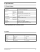
Specification 2. Specification 2-1 Printer Engine Thermal Inkjet Technology 1-pen & Print Head Swapping Type Speed Color (*1) 3ppm at Draft Mode Mono (*2) 8ppm at Draft Mode Color 600 x 600 dpi (1200 x 1200 dpi Addressable) Mono 600 x 600 dpi (1200 x 1200 dpi Addressable) Resolution Printing Width 203mm Automatic 130 Sheets of 20lb cut sheets Manual Tray No Feeding Method Emulation Host Based Printing (GDI) Printer Driver Windows 3.1/3.
Specification 2-3 Facsimile GENERAL Compatibility ITU-G3 Scan method CIS Scan width Max. 216mm, Effective: 210mm Scan Resolution 300 x 300 dpi Scan Speed 3 sec Feeding method Sheet-fed ADF 30 sheets Guide Document Input Guide Stacker Document Output Stacker (No Paper Stacker) Paper Tray BIN Type (No Manual Tray) Modem Speed 14.
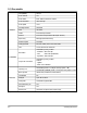
Specification 2-3 Facsimile (continued) TELEPHONE REPORT & LIST COPY One-touch Dial 20 Locations Speed Dial 50 Locations Chain Dial Yes Handset & Cradle Option On-hook Dial Yes, 1-Key Last Number Redial Yes, 1-Key Auto Busy Redial Yes No Power Operation UK : CALLING only, Other Country : No Hold & Mute No Pause Yes, Use Redial Key Ringer Volume S/W Option Setting (4Steps) Tone/pulse Select S/W Option setting (Pulse for NPO) Flash UK : Yes, Other Country : No Mercury No DRPD
Specification 2-4 Scanner Compatibility TWAIN Technology Platen CIS Light Source for Color CIS RGB LEDs (Line Order Control) 2-5 Power & Size Power Source USA : 110V 60 Hz, UK/GER : 220V 50 HZ Dimensions (W x D x H) 360 x 325 x 190 mm (Without Handset) Weight 5.
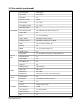
3. Installation 3-1 Handset and Handset Cradle Cradle 00000000000000000000000 1. Plug one end of the coiled cord into the jack on the handset. 3. Attach the handset cradle to the main body. Insert the two tabs of the cradle into the slots on the left side of the main body as shown, and push it up. Handset 0000000000 2. Plug the cradle’s modular cords into the modular jacks on the left side of your machine. Note: If you want to remove the handset, slide it down, then take it out.
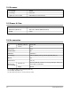
3-3 Document Exit Tray 1. Insert the two tabs on the document exit tray into the slots on the front of your machine. Document exit tray 2. Fold out the extender, if necessary. Extender 3-4 Telephone Line Plug one end of the telephone line cord into the TEL LINE jack and the other end into a standard phone wall jack. 000000 00000000 0000 000000 0000 3-5 Extension Phone (Optional) Plug one end of the modular cord into the EXT.TEL jack on the back of your machine.
3-6 AC Power Cord Plug one end of the cord into the back of the machine and the other end into a standard, grounded 3-prong AC power outlet. The machine turns on. All lamps on the control panel light up and the LCD displays ‘SYSTEM INITIAL’ then ‘PAPER OUT’. Load the paper as described on page 3-4. If you want to turn it off, unplug the power cord. Note : If documents are deleted from memory due to a power failure, the machine automatically prints out a Power failure report after power is supplied.
3-8 Loading Paper The LCD displays ‘PAPER OUT’ when paper is not loaded. You can load approximately 130 sheets of paper. 1. Pull the paper support on the paper bin all the way up. 3. Hold the left paper guide and move it to the right to match the width of the paper. Paper support 2. Fan the paper and insert the paper with the print side facing you. Paper Guide 3-9 Loading an Envelope You can load a standard or non-standard sized envelope. 1. Turn the envelope guide upright. 3.
3-10 Installing Print Cartridge 3-10-1 Print Cartridge 1. When you install a new print cartridge, press the Cartridge button on the control panel. The LCD displays ‘CHECK CARTRIDGE! PLEASE INSTALL’, and the print cartridge moves to the load position. If you install a color cartridge, use ‘Install Cartridge’ tab in the SF4400 Control Program on your PC. 2. Lift the control panel 1 with your hand and open the cartridge compartment cover 2. 3. If you are replacing a used cartridge, remove the old cartridge.
6. Insert the print cartridge in the carrier. 8. After installing the print cartridge, close the cover and replace the control panel. 9. Use ‘Install Cartridge’ tab on your PC for a color cartridge. The LCD displays ‘THE CARTRIDGE IS 1:NEW 2:USED’. 10. Choose ‘1:NEW’ by using the F or E button, or by pressing the 1 button. 11. Press the Cartridge button. The LCD displays briefly ‘MONO INSTALLED’ (or ‘COLOR INSTALLED’ for color print cartridge). Use ‘Install Cartridge’ tab on your PC for a color cartridge.
3-10-2 Print Cartridge Storage Unit The print cartridge storage unit provides a convenient place to store an extra black or color print cartridge, and prevents an opened cartridge from drying out. TO STORE A PRINT CARTRIDGE IN THE STORAGE UNIT Insert the print cartridge into the storage unit and slightly push it down. TO REMOVE A PRINT CARTRIDGE FROM THE STORAGE UNIT Push the cartridge slightly down and pull it toward you.
4. Disassembly and Reassembly 4-1 General Precautions on Disassembly When you disassemble and reassemble components, you must use extreme caution. The close proximity of cables to moving parts makes proper routing a must. If components are removed or replaced, any cables disturbed by the procedure must be replaced as close as possible to their original positions. Before removing any component from the machine, note the cable routing that will be affected.
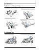
Disassembly 4-3 Top Cover Ass’y 1. Lift the control panel and open the print cartridge compartment cover. Remove the white roller ass’y. Remove the six screws shown below. Note: When you reassemble the top cover ass’y, make sure the tabs in the bottom of the ass’y fit into the slots in the base ass’y. Cartridge compartment cover Control panel Base ass’y 2. Remove the print cartridge. Remove the two screws shown below and take out the top cover ass’y.
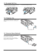
Disassembly 4-4 Rear Cover Ass’y 1. Holding the paper guide, move it in the direction of arrow. 3. Holding the rear cover ass’y, take it out by rotating it to be released properly. Rear cover ass’y Paper guide 2. Remove the storage Unit, and remove the six screws shown below.
Disassembly 4-5 Base Ass’y 4-5-1 Rollers (ADF Roller, Drive Roller, Exit Shaft) Drive roller CIS harness 1. Before you disassemble the rollers, you should remove: – Top Cover Ass’y (see page 4-2) CIS ass’y 2. Take out the rollers from the base ass’y. ADF roller Drive roller 4. Turn the CIS ass’y over. Remove the one screw to release the CIS from the bracket. Note: Be careful not to lose the springs. CIS Exit shaft Mono Bracket Note : Clean the surface of the rollers with ethyl alcohol.
Disassembly 3. Remove the two screws as shown below and take out the scan motor ass’y. 4-5-3 Scan Motor 1. Before you disassemble the CIS, you should remove: – Top Cover Ass’y (see page 4-2) – Rear Cover Ass’y (see page 4-3) 2. Unplug the motor connector from the main PBA. Make sure the harness is released from two hooks securing the harness as shown below. Hook1 Scan motor ass’y 4. Remove the two screws securing the motor to the motor bracket.
Disassembly 4-5-4 SMPS 1. Before you disassemble the SMPS, you should remove: – Rear Cover Ass’y (see page 4-3) 4. Remove the one screw securing the ground wire to the main frame as shown. Make sure the harness is released from the hook securing as shown below. 2. Unplug the SMPS connector from the Main PBA. Make sure the harness is released from the hook as shown below. Hook Ground wire 2 SMPS Main frame 5. Pushing down the hooks on both ends, pull out the SMPS. Bracket-LF SMPS connector 3.
Disassembly 4-5-5 LIU PBA 1. Before you disassemble the LIU PBA, you should remove: – Rear Cover Ass’y (see page 4-3) 3. Pulling the snap fits locking the PBA outward, push up the LIU PBA. 2. Remove the one screw securing the ground wires to the bracket. LIU PBA Bracket-LF LIU ground wire SMPS ground wire 4. Unplug all the connectors from the LIU PBA.
Disassembly 4-5-6 Speaker and Buzzer* 4-5-7 Volume PBA 1. Before you disassemble the speaker and buzzer, you should remove: – Printer Unit (see page 4-11) 1. Before you disassemble the Volume PBA, you should remove: – Top Cover Ass’y (see page 4-2) 2. Remove the four screws securing the speaker and buzzer. 2. Unplug the one connector and remove the one screw shown below, and take out the PBA.
Disassembly 4-6 OPE Ass’y 4-6-1 ADF Rubber Pad 1. Open the OPE unit. 2. Insert a flat blade screw driver into the slot as shown below, and release the latches. Take out the rubber holder, sheet ADF and the rubber pad. Notes: • When you reassemble the rubber pad, be sure that the rubber pad, sheet ADF and holder fit into the guide boss and the holder latches fit into the corresponding hole. Then push firmly until it clicks.
Disassembly 4-6-2 OPE Unit 1. Before you disassemble the OPE unit, you should remove: – Top Cover Ass’y (see page 4-2) – Rear Cover Ass’y (see page 4-4) 3. Turn the tie stopper 90 degrees as shown below and take out the OPE unit. OPE unit 2. Unplug the OPE (NPO) connector from the LIU PBA.
Disassembly 4-6-3 Roll Pinch 4-6-4 OPE PBA 1. Before you disassemble the roll pinch, you should remove: – OPE Unit (see page 4-9) 1. Before you disassemble the OPE PBA, you should remove: – OPE Unit (see page 4-9) 2. Remove the four screws securing the OPE unit. 2. Remove the four screws securing the OPE unit. 3. Turn the upper scan frame of the OPE unit over. 3. Remove the nine screws and take out the PBA and LCD. 4. Remove the three screws and take out the spring pinch.
Disassembly 4-7 Printer Ass’y 4-7-1 Printer Unit 1. Before you disassemble the printer unit, you should remove: – Top Cover Ass’y (see page 4-2) – Rear Cover Ass’y (see page 4-3) 3. Remove the ASF feeder ass’y from the printer unit by pushing the tab inward and take the ass’y out in the direction of arrow. 2. Remove the two screws securing the printer unit, and unplug the six connectors from the Main PBA. Take out the printer unit.
Disassembly 4-7-2 ASF Feeder Ass’y 1. Before you disassemble the ASF feeder ass’y, you should remove: – Rear Cover Ass’y (see page 4-3) 4. Remove the one screw, then remove pick up shaft from the ASF frame while pushing it to the right to disengage the gear. 2. Unplug all connectors from the Main PBA and remove the two screws shown below. Pick up shaft Note : When you reassemble the ASF feeder ass’y, insure the harness in the line feed motor is not pinched or shorted.
Disassembly 4-7-3 Home Ass’y 4-7-5 Base Frame Ass’y 1. Before you disassemble the home ass’y, you should remove: – Printer Unit (see page 4-11) 1. Before you disassemble the base frame ass’y, you should remove: – Printer Unit (see page 4-11) – Carrier Ass’y 2. Pushing the both ends of the home ass’y, take out the ass’y in the direction of arrow. 2. Remove the friction ass’y, then take out the actuator feed. 3. Pull out the base frame ass’y.
Disassembly 4-7-4 Carrier Ass’y 4-7-6 Feed Roller Ass’y 1. Before you disassemble the carrier ass’y, you should remove: – Printer Unit (see page 4-11) 1. Before you disassemble the feeder roller ass’y, you should remove: – Printer Unit (see page 4-11) – Carrier Ass’y – Base Frame Ass’y 2. Remove the cable holder. Remove the one screw on the right side of the main frame, and remove the spring. Then take out the carrier shaft. 2. Remove the bearing feed from the main frame.
Disassembly 4-7-7 Line Feeder Bracket Ass’y 1. Before you disassemble the line feeder bracket ass’y, you should remove: – Printer Unit (see page 4-11) – Feeder Roller Ass’y (see page 4-12) 3. Unplug all connectors from the Main PBA. 4. Pull the sensor lever towards you and take out the Main PBA. 2. Remove the two screws and take out the LF bracket ass’y. Main PBA LF bracket ass’y Sensor lever 4-7-8 Main PBA 1.
6. Circuit 6-1 Main PBA 6-1-1 Summary The main circuit that consists of CPU, MFP controller (built-in 32bit RISC processor core: ARM7TDMI) including various I/O device drivers, system memory, scanner, printer, motor driver, PC I/F, and FAX transceiver controls the whole system. The entire structure of the main circuit is as follows: Fig.6-1-1.
6-1-2 MFP Controller (KS32C6200 : U16) MFP Controller consists of CPU(ARM7TDMI RISC processor), 2K-byte cache, data and address buses, serial communication part with LIU(Line Interface Unit), OPE(OPERATION PANEL) print head controller, parallel port interface, external DMApart to receive data from external color image processor (SCANIP:U18), LF/CR motor diver controller and I/O controller. 6-1-2-1. SYSTEM CLOCK The internal clock frequency is 30MHz.
6-1-2-3, LIU(Line Interface Unit) Serial Communication Part UART (Universal Asynchronous Receiver/Transmitter) at KS32C6200 enables the main and LIU, main and OPE to transmit serial data. The block diagram of UART is as follows: (Fig.6-1-2) KS32C6200 has 2 UART channels. The baud rate is 9600bps. Fig.6-1-2. UART BLOCK DIAGRAM Fig.
6-1-2-4 EXTERNAL DMA It brings data from an external device (SCANIP:U18) using DMAchannel 0. DMAREQUEST sent from an external device to KS32C6200 activates DMA ACKNOWLEDGE signal and drives DMAchannel 0 to produce CHIP SELECT and READ STROBE (/RD) at the external device and bring data from it. It generates address of destination memory, CHIP SELECT and WRITE STROBE (/WR) in order to move this data into destination memory, and then stores the data. Fig.
6-1-2-5. DRAM CONTROLLER 6-1-2-6. PARALLEL PORT INTERFACE As KS32C6200 has DRAM controller in it, DRAM can be connected with external memory. The control mode of DRAM controller enabling EARLY WRITE, NORMALREAD, PAGE MODE, and BYTE/HALF WORD ACCESS supports EDO DRAM as well as normal DRAM. DRAM READ/WRITE signals are /RD and /WR signals used to control system buses. It supports CAS BEFORE RAS for DRAM REFRESH and self-refresh mode for DRAM backup.
Fig.6-1-6 ECP Hardware Handshaking Timing (forward) Fig.
6-1-2-7. INKJET HEAD CONTROLLER This part produces major control signals used to drive INKJET head. It consists of signals to drive head nozzles, /HGA[13:1], HOE[16:1], /FAULTTEST, /HEAD-EN, and BIASOFF, and consists of signals to check the status of the head, HEAD-DATA. It has double height print head, system 208 nozzles for mono and 192 nozzles for color, and uses /HGA[13:1], HOE[16:1] signals and /HEAD-EN to drive these nozzles. Fig.5-1-8 is timing diagram of each signal. Fig.
Fig.6-1-9. Timing Diagram for Each Nozzle The above control signals are sent to head driver and the head driver converts these signals to the level (+11.75V) to drive head nozzles. according to the kind of motors. Though full step, half step and software control are possible for both, bi-polar CR motor is controlled half step and LF motor is controlled half step and quarter step here. 5-1-2-8.
5-1-2-9. I/O PORT FOR KS32C6200 PIN NAME DESCRIPTION FOR STATE PIN NO I/O PORT NAME GOP0/TXD0 122 p LIT_TXD Serial Data Output to ILIU GOP1/TXD1 124 p OPE_TXD Serial Data Output to OPE GOP2/nEDACK 139 p nXDACK GOP3/TONE 149 p KEYCLICK Keyclick Tone GOP4/nRST0 150 p nRST0 Watchdog Reset Signal Output GOP5/nIOWR1 134 p nFAULT_TEST – Head Fault Test Enable GOP6/nIOWR2 155 p RX_CTL Line for RX. Line for TX.
6-1-2-10. RESET CIRCUIT As for this product, there are 2 power resets of primary reset(/F-POR) and secondary reset(/POR) and also reset by watchdog timer (/RSTO). Primary reset is used to initialize flash memory when the system is turned on, while secondary reset is used to initialize the whole system by initializing MFP controller (KS32C6200) after primary reset.
6-1-4-2. SCAN RESOLUTION 6-1-3 System Memory System memory consists of 512KB flash memory, 2MB DRAM, and 32KB SRAM. Flash memory, DRAM and SRAM are selected by each CHIP SELECT (/ROMCS, /RAS0, /RAS1, /LCAS, /UCAS, /RAMCS), and data is accessed half word (16bits) by half word and one byte (8bits) by one byte. DRAM is designed to be able to add 2MB to the basic 2MB so that buyers can make their options.
6-1-4-4. IMAGE PROCESSING 1) Image signal input: CIS output signals are offset at 1-4V with about 2.8V white level. Optimum input level of SCANIP is 1.5V offset and 3.5V white level. So OPAMP is used to design interface circuit of SCANIP.
6-1-4-5 I/O PORT FOR SCANIP REGISTER NAME PIN NAME for ASIC I/O PORT NAME GPI0 I GPI1 H L OK2PRINT Head OK Head NG I HOME_SEN Head parking – GPI2 I reserved GPI3 I nP_EXIT – Paper Detected GPI4 I P_EMPTY Paper empty – GPI5 I nRING_DET – Ring Detected GPI6 I nHOOK_OFF – H/S hook off GPI7 I RY/nBY Flash Ready Flash Busy GPO0 p reserved GPO1 p nOPE_RST OPE reset off OPE seset on GPO2 p BLED(C/–)1 BLED On BLED Off GPO3 p RLED(C/–)1 RLED On RLED Off G
6-1-5 Printer 6-1-5-1. GENERAL It drives inkjet head to print printing data received from the computer or fax data coming through the line. It roughly consists of head driver, head controller, and the ambient temperature sensor. Fig.61-11. Block Diagram of Printer shows the entire structure. 6-1-5-2. HEAD DRIVER (U26, U27, U32, U22) This part drives and inks inkjet head. Color inkjet head drives 192 nozzles, while mono inkjet head drives 208 nozzles. Mono inkjet head is composed of 16 groups of 13 nozzles.
6-1-5-3. HEAD CONTROLLER This part consists of +22V Power Controller to control head driver, Fault Test, Head Detection, Substrate Heating and ambient Temperature Sensor. It checks and controls head driver and ink cartridge. Fig.
• +22V Power Controller If you insert power cords, the main board will be supplied with power. /POR signal put out through reset circuit activates MFP controller (K32C6200:U16) and MFP controller puts out external circuit reset signal /RST-OUT. This / RST-OUT signal and Vrefx (+2.5V) divided through +30V are impressed to the input terminal of the comparator, putting out +22V if the output of the comparator is “high” or getting turned off if “low”.
Color Head 70°C Fig.6-1-14. Temperature around Color Head • HEAD DETECTION CIRCUIT Babbage ink cartridge has 8-bit mask ROM I.D. to check the type of cartridge. In order to detect the head, HSM signal is used as ENABLE signal and BA3 signal as START & STOP BIT, and BA1 and BA2 as clock signal of each bit, and ID signal in the cartridge is put in HEAD-DATAport of KS32C6200 through BSF line. With each bit controlled, 8bit I.D data is read and STOP bit is put out of BA3(LOAD) port. Then it finishes.
• SURROUNDING TEMPERATURE SENSOR DS1621S(DALLAS SEMI.) is applied to read the temperature around ink cartridge. It is used to get optimum inking quality by keeping the viscosity of ink in the cartridge in the specified lerel. The way to read temperature is similar to EEPROM, controlled by THM-CLK, THM-DATALINE. Digital thermometer to check the surrounding temperature is assembled along with home sensor in the frame of assembly CR.
Fig.6-1-17.
6-1-5-5. INK CARTRIDGE • PIN ARRAY OF MONO INK CARTRIDGE There are 208 heater chips in mono ink cartridge.
• PIN ARRAY OF COLOR INK CARTRIDGE There are 192 heater chips in mono ink cartridge. One cartridge has 64 Cyan, 64 Magenta, 64 Yellow heaters and (64 x 3 colors) 192 nozzles.
6-1-6 Motor Driver 6-1-6-1. GENERAL 6-1-6-2. CR (CARRIAGE RETURN) MOTOR DRIVING CIRCUIT This product use 3 stepper motors, i.e. CR(Cartridge Return) motor and LF(Line Feed) motor, TX (Transmission) motor. CR motor moves left and right all-in-one carriage of inkjet head and shuttle scanner. It helps the printer print accurately on the paper. LF motor is driven to feed and eject paper for printing and to feed and eject documents to read for scanning.
6-1-6-3. LF (LINE FEED) MOTOR DRIVING CIRCUIT LF motor is driven to feed and eject documents and paper. - Motor Type: stepper motor, bi-polar - Driving Voltage : +30V - Winding Resistance : 12Ω ± 10% - Driving IC : PBL3717A × 2 LFIA1 LFIA0 CURRENT(mA) OPERATION L L 670 When feeding document/paper L H 400 When ejecting document/paper X H 0 No current REMARK 6-1-6-4. TX(TRANSMISSION) MOTOR DRIVING CIRCUIT TX Motor is driven at maximum 1200pps when feeding or ejecting sheets.
6-1-7 FAX Transceiver 6-1-7-1. GENERAL 6-1-7-3. TRANSMITTER This circuit processes transmission signals of modem and between LIU and modem. This circuit is added only to SmartJet 2000, SF-4300C. This circuit processes transmission output, analog signal of modem(KS16117). Output signal in each mode goes out of modem (TXOUT:U15-44). After D/Asignals are smoothed and filtered through active filter (U12-2), they are buffered under OPAMP(U12-6) and put out to LINE through LIU board. 6-1-7-2.
6-2. OPE PBA 6-2-1. SUMMARY 6-2-2 OPE Circuit OPE Board is separated functionally from the main board and operated by the micom(Z8601) in the board. OPE and the main use UART (universal asynchronous receiver/transmitter) channel to exchange information. OPE reset can be controlled by the main. OPE micom controls key-scanning and LCD and LED display, detects documents and senses SCAN position.
6-3 LIU PBA 6-3-1 Summary 6-3-4 Dialer LIU(Line Interface Unit) circuit added only to SF-4500, SF-4500C is controlled by the main circuit. It monitors telephone line and helps interface between the system and the telephone line. It uses 1-LIU(STI9510) to control the whole LIU, MODEM/LINE INTERFACE, RING SIGNAL DETECTOR, DIALER, LINE CURRENT DETECTOR, and SERIAL INTERFACE. 6-3-4-1. MF DIAL 6-3-2 Modem/Line Interface This is the path through which transmitted and received data of modem is put in and out.
6-3-6 Serial Interface • This part does serial communication with MFP controller of the main board (MAIN PBA:U16) that controls the whole system. It controls LIU by giving and taking all control orders and line status. • U3-11 RxD : Schmitt Trigger input, Receiving terminal. • U3-29 TxD : Open Drain output terminal • Standard UART communication - Baud Rate : 9600bps - Start, Stop bit : 1bit each - Data bits : 8 bit - Parity bit : none 6-3-7 MAJOR FUNCTIONS OF PARTS 1) U3 : STI9510 - Key part of LIU board.
6-4 SMPS 6-4-1 Block Diagram of Power Circuit Refer to the following block diagram. POWER SUPPLY 6-4-2. Specifications of Power Circuit 6-4-2-1. INPUT CONDITIONS 120V 220V Free Voltage AC120Vac (a) AC220–240Vac (a) AC110–240Vac (a) AC85–135Vac (b) AC180–270Vac (b) AC85–270Vac (b) 1 Input Rated Voltage 2 Input Voltage Turning Range 3 Rated Grequency 60Hz 50–60Hz 50–60Hz 4 Frequency Range 57–63Hz 47–63Hz 47–63Hz 5 Input Current 0.5Arms 0.3Arms 0.
6-4-2-2. OUTPUT CONDITIONS NO ITEM CH1 CH2 CH3 1 RATED OUTPUT VOLTAGE +5.0V +11.75V +30V 2 RATED OUTPUT CURRENT 0.5A 0.8A 0.5A 3 MAXIMUM LOAD CURRENT 0.8A 1.3A 0.76A 4 LOAD CHANGE RANGE 0.1 ~ 0.8A 0.03 ~ 1.3A 0.05 ~ 0.76A 6-4-3. Power Circuit 6-4-3-1 INPUT 6-4-3-2 DRIVING CIRCUIT (START-UP CIRCUIT) This product is equipped with a three-wire grounding-type power inlet. Insulation is class 1.
6-4-3-4 OCP CIRCUIT (OVER CURRENT PROTECTIVE CIRCUIT) If a short in secondary load terminal or a short inside power device causes excess current, power consumption increases. Then it increases current of power transistor. The current of power transistor increases linearly when it is on. This current is detected by sensing resistance and is impressed to excess voltage protective circuit of PWM control circuit through RC integration circuit where over current protection is built in.
6-5-2. Home Sensing Circuit This circuit senses whether carriage is at home or not. This function is carried out when the system is turned on or when the head is capped. Photo interrupter is used as a home detecting sensor, attached to the back of the carriage. When the carriage moves left and right, output is “high” if the frame rib covers the center of the sensor and “low” if it is out of home.
8. Troubleshooting 8-1 SCANNER 8-1-1. COPY PROBLEM ITEMS TO BE CHECKED HOW TO SOLVE White Copy • Check shading profile. • Check white Ref. value and black Ref. value. • Check CIS signal input level. • Remake shading profile in the tech mode. • Replace U17 if it is defective. (white Ref. =3.0V. black Ref=1.4V) • Check if it is 3.0V when operating and 1.5V when idle. If defective, replace CIS. Black Copy • Check shading profile. • Check if CIS LED is on/off. • Check white ref.value and black Ref.value.
8-1-3 Service Mode 8-1-3-1 HOW TO ENTER SERVICE MODE In service (tech) mode, the technician can check the machine and perform various test to isolate the cause of a malfunction. To enter the service (tech) mode, press MENU, #, 1, 9, 3, 4 in sequence, and the LCD briefly displays ‘TECH’, the machine has entered service (tech) mode. While in service (tech) mode, the machine still performs all normal operations.
8-1-4-2 OPTIONS IN SYSTEM SETUP MODEM TEST The modem will send various transmit signals on the telephone line you can check the fallowing: • FSK tect • Tones : 1100Hz, 1650Hz, 1850Hz, 2100Hz • G3 training : 14400, 12000, 9600, 7200, 4800, 2400bpi DTMF DTMF (Dual Tone Multiple Frequency) signal can be checked. • 1, 2, 3, 4, 5, 6, 7, 8, 9, 0, *, # Fig.8-1-4-2-1 Mono Shading Waveform ADJUST SCAN LED ON TIME • It is used to adjust the anount of light of CIS.
RINGER VOLUME •Refer to User’s Guide. HOME SETTING •Refer to User’s Guide. PROGRAM DOWNLOAD • It is used to download ROM files into the machine using its flash ROM. If you download CIS or the main board again, you should adjust SCAN LED ON TIME. • Download Sequences: ➀ Press the ‘START’ key in ‘PROGRAM DOWNLOAD?’ then the display shows ‘ARE YOU SURE? 1. YES 2. NO’ ➁ Press the ‘I’ key ➂ Download ROM files from a PC that can be connected with Pallel cable (IEEE 1284).
8-1-5-2 SYSTEM DATA 8-1-5-3 CHANGING SYSTEM DATA MODEM SPEED Press MENU and one-touch button 01 system data. Then press 1 to choose ‘Tech’. Press ▲ or ▼ repeatedly to select the desired system data. When the desired system data appears, enter the corresponding information to change the status of the selected function. Press STOP to return to the date and time display. Default = 14400 bps Select baud rate of 14400, 12000, 9600, 7200, 4800, or 2400 bps.
8-2 FAX/TELEPHONE Precautions PROBLEM ITEMS TO BE CHECKED HOW TO SOLVE • When you pick up the handset: ➀ Check line cord connection and P3(LIU) connection. ➁ Check hook switch of H/B Cradle and D2(LIU) connection. ➂ Check the circuit around R2, Q1 and Q2 of LIU PBA. ➃ Can’t you hear dial tone though the line is engaged? • When you press “OHD” key: ➀ Check line cord connection. ➁ Check U7(main PBA), main LIU harness, and P1(LIU PBA).
8-3 Paper Feed PROBLEM ITEMS TO BE CHECKED HOW TO SOLVE ASF feeds paper but paper is not supplied to the engine. • Check if actuator feed operates perfectly. • Check if paper sensor is normal. • Replace actuator-feed, spring, or other defective parts. • Replace the paper sensor. ASF cannot feed paper. • Check if stopper clutch operates perfectly. • Check if too much paper has been supplied. • Check if pickup roller rubber of the ASF is worn out. • Replace stopper clutch assembly.
8-4. Printing Quality 8-4-1 White lines on letters or graphics. ■ Cause If nozzles in print head has a problem, white lines are marked on the print. ‘Self-Test printing’ will let you know if nozzles have fallen problems. If this line is broken, it confirms that nozzles have problems. ■ Solution 1) Run ‘print control panel’ to “clean cartridge” and check if nozzles have been blocked.
8-4-2 When Vertical lines are printed crookedly 2) Select the best one of the above samples and enter the number. 3) This function to align Vertical lines is available both for mono and color cartridges. ■ Cause : Vertical lines are printed crookedly if you do not “align Vertical lines” on the printer.
8-5. Defective Operation PROBLEM LCD does not display (operation panel) ITEMS TO BE CHECKED • Powered up? • VCC(+5v) M+4.5V? • Is the level of U16-130(_POR) high (more than +4V)? • Check Main to OPE harness and J3(main). • Is the level of U16-153 (_RST_OUT) high (more than +4V)? • Is the level of U18-31 (_OPE_RST) high (more than +4V)? • Check control signals of U16-124, 125(OPE_TXD, OPE_RXD). Cannot enter by keys(operation panel) • Refer to 4-7 of “LCD does not display”. • Check OPE key contacts.
PROBLEM Document Jam ITEMS TO BE CHECKED • Check document feeder. • Check the operation of TX motor. ➀ Check the control signals of U18105~110. ➁ Check the input signals and driving output of U23 and U24. HOW TO SOLVE • Remove jammed documents and insert it again. • ➀ If control signals are not made when other functions are normal, replace the main PBA ➁ If driving output is defective when input signals are normal, replace U23 and U24.
9.
NO 0 1 2 3 4 5 6 7 8 9 10 C1 11 12 13 14 15 16 17 18 19 20 21 22 23 24 25 26 27 28 29 30 31 32 33 34 35 36 S1 9-2 DESCRIPTION SF-4500 Msys4700 MJ-4500 SF-4500C Msys4800 MJ-4500C UNIT-Cartridge(M) UNIT-Cartridge(C) Dummy-Cradle Unit-Handset Unit-Cradle Curl cord Unit-OPE Ass’y White-Roller Ass’y Bushing-White Roller-CIS Gear-Drive (B4) Ring-C Top-Cover Ass’y Cover-Top Label-Nameplate Label-Replace Label-Cleaning Dummy-Chute Chute Guide DOC L Guide DOC R Door Spring Curve Gear pinion L
9-2 Unit-OPE Ass’y Samsung Electronics 9-3
NO 0 1 2 3 4 5 6 7 8 9 10 11 12 13 14 15 16 17 18 19 20 21 22 23 24 25 26 27 28 S1 S2 9-4 DESCRIPTION Unit-OPE Ass’y Cover-Address Paper-Address COVER-LCD COVER-LCD COVER-OPE KEY-Mode KEY-OT KEY-SCROLL KEY-STOP KEY-COPY KEY-START Rubber-OT KEY-OHD KEY-TEL Rubber-Scroll Rubber-TEl PBA-OPE PBA-OPE GND WIRE (OPE) Spring-Pinch Ass’y Ground-Sensor Spring-Coil Support-ADF Lever-Sensor Frame-Upper Roll-Pinch Shaft-Pinch Holder-Rubber Rubber-ADF Cable-Clamp Screw-Taptite M3u8L Screw-Taptite M2.
9-3 Unit-Base Ass’y Samsung Electronics 9-5
NO 0 1 2 3 4 5 6 7 8 9 10 11 C1 12 13 14 15 16 17 C1 C2 18 19 20 21 22 23 24 25 26 27 28 29 30 31 32 9-6 DESCRIPTION Unit-Base Ass’y SMPS SMPS LIU PBA Harness CIS (M) Harness CIS (C) Harness CIS GND CIS (M) CSI (C) Bracket CIS (C) Bracket CIS (CC) Spring CIS (2) Harness LIU/Cradle Shaft Exit Drive Roller Ass’y Gear Drive (B4) Ring-C (ID3) ADF Roller Ass’y Roller ADF Shaft-ADF Spring-Clutch Gear-ADF Bushing-holder Ring-C (ID3) Ring-C (ID5) PBA-R/T/P Harness-LIU/RINGER Spring-GND Harness-L
NO 33 34 35 36 37 38 39 40 C2 S1 S2 S3 DESCRIPTION Bracket-Motor Motor-Tx Gear-Spur Gear-17/35 Gear-20/33 Gear-Idle25 Gear-17/35 Gear-17/27 Ring-C (ID3) Screw-Tapping, M3 u L8 Screw-Tapping, M2.
TOP 9-4 Engine-Ass’y 9-8 Samsung Electronics
NO 0 1 2 3 4 5 6 7 8 9 10 11 12 13 14 15 16 17 18 19 20 21 22 23 24 25 26 27 28 29 30 31 32 33 34 35 36 37 38 39 40 41 42 DESCRIPTION Engine-Ass’y PBA-Main PBA-Main Carriage Ass’y Frame-CR Rubber-Contact Craddle Head Latch-Head Spring-CS Deflector-Guide Harness-FPC Belt-Timing PBA-SUB Sensor Holder FPC Frame Base Ass’y Frame Base Pulley Exit Rubber Pulley Spring-Ring (0.
NO 86 87 88 89 90 91 92 93 94 95 96 97 98 99 100 101 102 S1 S2 S3 S4 S5 S6 DESCRIPTION Cam-pick up FINGER-ASF Spring-FINGER Spring-FINGER LEVER Bracket-FINGER Lever-FINGER Rubber-Pick Up Roller-Idle Shaft-Pick Up Actuator PE Photo-Interrupter Harness-PES Bearing-Feed “R” Spring-Return Lever Lever-Return Bushing-Lever Guide-Edge Screw-Taptite, M3 u L6 Screw-Taptite, M3 u L6 Screw-Taptite, M3 Screw-Machine, M3 u L6 Screw-Taptite, M3 Screw-Taptite, M2.
9-5 Unit Handset 9-12 Samsung Electronics
NO 0 1 2 3 4 5 6 7 8 9 10 11 12 S1 DESCRIPTION Unit-Handset Handset-Upper Weight-balance PBA-Hook Harness, CBF-JACK MIC-CONDENSOR RMO-Rubber MIC DIODE-Zener Unit-Fixing Audio-Receiver RING-op Handset-Lower Hole-dummy Screw-Taptite(M3u8L) Samsung Electronics SEC CODE JG96-00680B JG72-40942B JG70-10694A JF92-00682A JF39-41070A 3003-000102 JG73-40508A 0403-000142 GB70-10500A 3009-00101 6044-000138 JG72-40943B JF73-40512C 6003-000168 Q’TY 1 1 1 1 1 1 1 1 1 1 1 1 1 6 AVALABLE SVC PART v 9-13
9-6 Unit-Cradle 7 9-14 Samsung Electronics
NO 0 1 2 3 4 5 6 7 S1 S2 DESCRIPTION Unit-Cradle Cradle-Upper Cover-Hook Hook-PBA LINE-CO(210mm) LINE-CO(170mm) Cradle-Lower Cradle Cap Screw-Taptite(M3 u L6) Screw-Taptite(M3 u L8) Samsung Electronics SEC CODE JG96-00681B JG72-40944B JG72-40946B JG92-00587A JG39-50504A JG39-50503A JG72-40945B JB72-41234A 6003-000165 6003-000168 Q’TY 1 1 1 1 1 1 1 1 1 2 AVALABLE SVC PART v IVORY BLK 9-15
10.
NO 1 DESCRIPTION Box(p)-Master 2 SF-4500 Msys4700 SF-4500C Msys4800 MJ-4500C BAG-SET Cushion “L” Cushion “R” Unit-Cartridge (M) Unit-Cartridge (C) User’s Manual Stacker-Tx Ass’y CurL cord CurL cord CD-ROM LINE-CORD LINE-CORD POWER-CORD Man (card)-BITS BAG-Accessory Handset BAG-Cradle Cradle Tam Cord Spacer ASF Paper Address Application Manual WinFax LITE 4.0 Disk 1 WinFax LITE 4.
11.
NO SEC CODE 81 2007-000941 R-CHIP, 47Kohm, 5%, 1/10W, DA, TP, 2012 DESCRIPTION 2007-000964 R-CHIP, 5.1Kohm, 5%, 1/10W, DA, TP, 2012 PART NUMBER RC2012J473CS VENDER SEM, ROHMK Q`TY REFERENCE 7 R138, R151, R180, R235, 8 R105, R107, R111, R134, R144, R250, R266, R274 82 RC2012J512CS SEM, ROHMK R146, R231, R232 83 2007-000964 R-CHIP, 5.1Kohm, 5%, 1/10W, DA, TP, 2012 RC2012J512CS SEM, ROHMK 3 R248, R259, R264 84 2007-000981 R-CHIP, 5.
NO SEC CODE DESCRIPTION PART NUMBER VENDER Q`TY REFERENCE 113 2203-000476 C-CHIP, 1uF, +80-20%, 16V, Y5V, TP, 2012 CL21F105ZONC SEM, MURATA, AVX 2 C137, C138 114 2203-000595 C-CHIP, 220pF, 5%, 50V, NPO, TP, 2012 CL21C221JBNC SEM, MURATA, AVX 4 C101, C118, C131, C286 115 2203-000634 C-CHIP, 22pF, 5%, 50V, NPO, 2012 CL21C220JBNC SEM, MURATA, AVX 8 C106, C107, C110, C114, C208, C212, C217, C230 116 C-CHIP, 22pF, 5%, 50V, NPO, 2012 CL21C220JBNC SEM, MURATA, AVX 5 117 2203-000661 2
11-2 SF-4500C/Msys4800/MJ-4500C Main B’d Parts List NO SEC CODE DESCRIPTION PART NUMBER VENDER Q`TY REFERENCE 1 0401-000116 DIODE-SWITCHING, MMSD914T1, 100V, 200mA, 225mW, 4nS MMSD914T1 MOT 3 D103, D104, D106 2 0401-001003 DIODE-SWITCHING, MMBD6050LT1, 70V, 200mA, 225mW, 4n MMBD6050LT1 MOT 2 D109, D110 3 0402-000199 DIODE-RECTIFIER, EGL41B, 100V, 1A, DO-213AB EGL41B GI 1 D111 4 0403-000287 DIODE-ZENER, MMBZ5251B, 22V, 5%, 225mW, SOT-23 MMBZ5251 MOT, MATSU 1 ZD101 5 0404-00011
49 2007-000290 R-CHIP, 100ohm, 5%, 1/10W, DA, TP, 2012 RC2012J101CS SEM, ROHMK 7 50 2007-000290 R-CHIP, 100ohm, 5%, 1/10W, DA, TP, 2012 RC2012J101CS SEM, ROHMK 7 R300, R301, R308, R309, R310, R311, R313 51 2007-000297 R-CHIP, 10Kohm, 1%, 1/10W, DA, TP, 2012 RC2012F1002CS SEM, ROHMK 5 R103, R245, R253, R297, R306 52 2007-000300 R-CHIP, 10Kohm, 5%, 1/10W, DA, TP, 2012 RC2012J103CS SEM, ROHMK 8 R152, R167, R183, R188, R195, R201~R203 53 2007-000300 R-CHIP, 10Kohm, 5%, 1/10W, DA, TP, 201
2007-001201 R-CHIP, 820ohm, 5%, 1/10W, DA, TP, 2012 RC2012J821CS SEM, ROHMK 1 R198 98 2007-001220 R-CHIP, 86.6Kohm, 1%, 1/10W, DA, TP, 2012 RC2012F8662CS SEM, ROHMK 2 R184, R187 99 2104-000111 VR-SMD, 10Kohm, 25%, 0.15W, TOP RH03A3A14R-10KB ALPS.
144 3301-000325 CORE-FERRITE BEAD, AB, 3.2u2.5u1.
11-3 SF-4500/4500C LIU B’d Parts List 1 0401-000140 DIODE-SWITCHING, 1N4148, 100V, 200mA, 500mW, 4nS, DO 1N4148T/R 2 0402-000339 DIODE-BRIDGE, W06F, 600V, 1.5A GI 3 0403-000139 DIODE-ZENER, 1N4734A, 5.6V, 5%, 1W, DO-41, TP 1N4734AT/R ITT, MOT 1 ZD8 4 0403-000155 DIODE-ZENER, 1N4748A, 22V, 5%, 1W, DO-41, TP 1N4748A ITT, MOT 1 ZD5 5 0403-000294 DIODE-ZENER, MTZ4.7B, 4.7V, 4.55-4.80V, 500 MTZ4.
53 2203-000455 CAP-CERAMIC, 1NF, 50V, 5%, 5M, NPO CL21C102JBNC SEM, MURATA 3 C1, C12, C22 54 2203-000595 CAP-CERAMIC, 220PF, 50V, 5%, 2012 CL31C221JBNC SEM, MURATA 7 C13~C17, 20, 21 55 2203-000609 CAP-CERAMIC, 22NF, 50V, 5%, 2012 CL21B223KBNC SEM, MURATA 1 C46 56 2203-000979 CAP-CERAMIC, 47NF, 50V, 5%, 2012 GRM40X7R473K50PT MURATA, AVX, KY 2 C19, C23 57 2203-001142 CAP-CERAMIC, 68NF, 50V, 5%, 2012 CL21B683KANC SEM, MURATA 2 C4, C18 58 2305-000218 CAP-FILM, MPEF, 1UF, 250V, 10%
11-4 Msys4700/4800 LIU B’d Parts List 1 0401-000140 DIODE-SWITCHING, 1N4148, 100V, 200mA, 500mW, 4nS, DO 1N4148T/R 2 0402-000339 DIODE-BRIDGE, W06F, 600V, 1.5A GI 3 0403-000139 DIODE-ZENER, 1N4734A, 5.6V, 5%, 1W, DO-41, TP 1N4734AT/R ITT, MOT 1 ZD8 4 0403-000155 DIODE-ZENER, 1N4748A, 22V, 5%, 1W, DO-41, TP 1N4748A ITT, MOT 1 ZD5 5 0403-000294 DIODE-ZENER, MTZ4.7B, 4.7V, 4.55-4.80V, 500 MTZ4.
53 2203-000455 CAP-CERAMIC, 1NF, 50V, 5%, 5M, NPO CL21C102JBNC SEM, MURATA 3 C1, C12, C22 54 2203-000595 CAP-CERAMIC, 220PF, 50V, 5%, 2012 CL31C221JBNC SEM, MURATA 7 C13~C17, 20, 21 55 2203-000609 CAP-CERAMIC, 22NF, 50V, 5%, 2012 CL21B223KBNC SEM, MURATA 1 C46 56 2203-000979 CAP-CERAMIC, 47NF, 50V, 5%, 2012 GRM40X7R473K50PT MURATA, AVX, KY 2 C19, C23 57 2203-001142 CAP-CERAMIC, 68NF, 50V, 5%, 2012 CL21B683KANC SEM, MURATA 2 C4, C18 58 2305-000218 CAP-FILM, MPEF, 1UF, 250V, 10%
11-5 SF-4500/4500C/Msys4700/4800/MJ-4500C Sensor B’d NO SEC CODE DESCRIPTION PART NAME VENDOR Q’T PART NUMBER 1 0604-001045 PHOTO-INTERRUPTER, TR, 0.
11-8 SF-4500/Msys4700 Others Parts List NO SEC CODE 1 0609-001030 DESCRIPTION PART NUMBER 2 GA39-10100A CBF-HARNESS, PAWER CORD, 220V 3 JB44-10504A SMPS, AMUNDSEN, AC/DC, 50W, HV, 220V AMUNDSEN-HV DYREL, KASHI 1 SMPS 4 JB59-10504A UNIT-CARTRIDGE, AMUNDSEN, 1382331, COLOR 1382331 LEXMARK 1 CARTRIDGE(COLOR) 5 JB59-10507A UNIT-CARTRIDGE, AMUNDSEN, 1362731, MONO 1362731 LEXMARK 1 CARTRIDGE(MONO) 6 JC39-40301H CABLE, MAIN-PRINTER, 36P A12H04879A SAMGI, SANCH 1 PRINTER CABLE 7
11-9 SF-4500C/Msys4800/MJ-4500C Others Parts List NO SEC CODE 1 0609-001030 DESCRIPTION PART NUMBER 2 GA39-10100A CBF-HARNESS, PAWER CORD, 220V 25056 (3AFUSE) KAWAS 1 3 JB44-10504A SMPS, AMUNDSEN, AC/DC, 50W, HV, 220V AMUNDSEN-HV DYREL, KASHI 1 SMPS 4 JB59-10504A UNIT-CARTRIDGE, AMUNDSEN, 1382331, COLOR 1382331 LEXMARK 1 CARTRIDGE(COLOR) 5 JB59-10507A UNIT-CARTRIDGE, AMUNDSEN, 1362731, MONO 1362731 LEXMARK 1 CARTRIDGE(MONO) 6 JC39-40301H CABLE, MAIN-PRINTER, 36P A12H04879A
11-10 SF-4500/4500C/Msys4700/4800/MJ-4500C SMPS B’d NO ITEM PART NUMBER DESCRIPTION Q`TY LOCATION 1 U1 1 U2 1 D1 1 D2 1 D3, D4 1 ZD1 1 ZD2 1 ZD3 800V 5A SAMSUNG KEC SAMSUNG KEC ROHM KOREA UNIZON MICRO SEMI SHINDENGEN MICRO SEMI SHINDENGEN ROHM KOREA UNIZON ROHM KOREA UNIZON ROHM KOREA UNIZON SAMSUNG 1 Q1 KSC5020-0 500V 3A SAMSUNG 1 Q2 TR-SWITCHING KSC1008-Y 80V 0.
NO 4004-A 4005 ITEM BEAD CORE PART NUMBER DESCRIPTION VENDER Q`TY LOCATION 1 B3 1 CON1 1 LUG2 1 LUG3 BAE EUN INALWAYS BUJEON YOUNHWA NAMYANG DONGHEUNG SUNGWON ASEA DONGYANG TRIAD 1 INLET 2 LF1,2 1 L1 1 PT1 2 FOR F1 TRIAD 1 F1 RTS3550S(R1) F-FB35T 3.
NO 1001 1001-A 1002 1002-A 1003 1003-A 1004 1004-A 1005 1005-A 1006 1006-A 1007 1007-A 1008 1008-A 1009 1009-A 1010 ITEM DESCRIPTION TR 500V 3A SAMSUNG KEC SAMSUNG KEC ROHM KOREA UNIZON MICRO SEMI SHINDENGEN MICRO SEMI SHINDENGEN ROHM KOREA UNIZON ROHM KOREA UNIZON ROHM KOREA UNIZON SAMSUNG SAMSUNG SAMSUNG 1011 TR-SWITCHING KSC1008-Y 80V 0.
NO ITEM PART NUMBER DESCRIPTION VENDER Q`TY LOCATION 1 C15 1 C10 1 C11 2011-A 2012 CAP-CERAMIC 2012-A 2013 CAP-MYLAR 2013-A 2014 CAP-MYLAR HCYB3A101KDS CCYV1H104ZF CGF1H104ZFK TY2A223J TS1H223J TY2A686J 100V 223J 50V 223J 100V 683J SEMCO SEMCO SAMHWA SAMHWA SAMHWA SAMHWA 2015 CAP-M.
NO 4005 ITEM PART NUMBER DESCRIPTION Q`TY LOCATION SAMHWA 2 B2,B4 NAMYANG 1 B3 SHINJIN 1 CON1 SHINJIN 1 LUG2 SHINJIN 1 LUG3 BAE EUN INALWAY BUEON YOUNHWA NAMYANG DONGHEONG SUGNWON DONGYANG ASEA TRIAD 1 INLET 2 LF1.
5.
7. Theory of Mechanism 7-1 Scanner Mechanism The scanner mechanism consists of components which feed, scan, and eject the documents that are to be copied or transmitted to a remote facsimile unit. These components and their functions are explained below.
7-2 Printer Mechanism 7-2-1 Paper Feed Mechanism 7-2-2 Home Ass’y This mechanism consists of the automatic sheet feeder (ASF), feed roller ass’y, line feed motor, and gear ass’y to move the paper in and out of the printer. When capping is released, the print cartridge carrier moves left and wipe the bottom of ink nozzle. After wiping it, the carrier rib pushes the rib in the dotted round as shown in the figure below. The home ass’y converts into standby mode.