Owner's Instructions SP-H700/H710/H500
Table of Contents Preparation Table of Contents Preparation Picture Adjustment Features and Design..............................................4 Selecting Picture Mode ......................................30 Caution on Lamp Use and Replacement ..............5 Custom Settings of the Picture ..........................31 Projector and Accessories Front/Upper Side and Accessories ........................8 Rear Side and Cables ........................................10 Remote Control Buttons ..........
Other Information Setting the Language ..........................................52 Storage and Maintenance ..................................72 Setting the Menu Position..................................53 Purchasing Optional Parts..................................73 Setting the Menu Translucency..........................54 Structure of Screen Menu ..................................74 Setting the Menu Display Time..........................55 Lamp Replacement ........................................
Features and Design Preparation Optical engine adopting advanced DLP technology ■ ■ ■ ■ SP-H700/SP-H710: DLPTM HD2+ DMD panel capable of 1280x720 resolution SP-H500: DLPTM ED2+ DMD panel capable of 1024x576 resolution 5X-speed color wheel designed to reduce digital artifacts 250W Lamp designed to improve luminance Vivid colors Features and Design ■ Quality picture tuning focused on improving color - this unit aims at realizing color coordinates that meet broadcasting standards on video production.
Caution on Lamp Use and Replacement The Projector lamp changes in nature depending on time of use and using environment. Refer to the installation and other recommended operational sections of the user’s manual to avoid rapid degradation of performance and deterioration of picture quality. The projector lamp requires regular replacement. ■ Free servicing will be offered within 90 days after purchasing of the product and within 300 hours of product use, if the problem is due to a defective lamp.
V I S U A L R E A L I S M Preparation Projector and Accessories ............................8 Installation and Basic Adjustments ..........
PROJECTOR AND ACCESSORIES Front/Upper Side and Accessories Front/Upper Side Preparation 11 10 9 8 7 1 Projector and Accessories 2 6 3 4 5 Indicators - TEMP (Red LED) - LAMP (Blue LED) - STAND BY (Blue LED) Refer to page 9 for details. 7 MENU Used to open the on-screen Menu. 8 POWER Used to turn the projector on or off. 2 Remote Control Signal Receiver 9 3 Focus Ring Used for Focus Adjustment. SOURCE Used to select input signals from the external sources.
Indicator Information : Turned On LAMP STANDBY : Turned Off Information Clearing Indicator Problems Classification Measure 1 Measure 2 Measure 3 Measure 4 NOTE State Measures Projector and Accessories If you press the POWER button on the remote control or projector, the screen appears within 30 seconds. The projector is in normal operating condition. The projector is warming up after POWER button has been pressed.
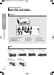
PROJECTOR AND ACCESSORIES Rear Side and Cables Rear Side Preparation 1 Projector and Accessories 7 2 3 4 8 5 6 9 1 Remote Control Signal Receiver 4 RS-232C port 7 AC Power Input 2 S-VIDEO Input port 5 DVI Input port 8 Power Switch 3 COMPOSITE Input ports 6 PC Input port 9 Component Input port Cables 10 Power Cord Connected to the wall outlet ∏. Video (COMPOSITE) Cable Connected to the connection port ˇ. PC Video Cable Connected to the connection port Ø.
PROJECTOR AND ACCESSORIES Remote Control Buttons 12 2 COMP.1 (Pages 24~26) Used to switch to COMPONENT 1 Mode. 3 COMP.2 (Pages 24~26) Used to switch to COMPONENT 2 Mode. 4 S-VIDEO (Pages 23, 26) Used to switch to S-VIDEO Mode. 5 P.SIZE (Page 37) Used to adjust the size of picture screen. 6 P.MODE (Page 30) Used to select Picture Mode. 7 STILL (Page 42) Used to see still images. 8 V.KEYSTONE (Page 46) You can use this function for trapezoidal adjustment of the image.
PROJECTOR AND ACCESSORIES Operating the Remote Control Operating Move/Select Button Preparation Projector and Accessories Move Menu Item (Up) Move Menu Item (Down) Setting the Adjustment (left), or move to upper item Select the current setting Inserting Batteries into Remote Control 1. Press on the part of the lid to remove it. 2. Insert two AAA-sized 1.5V batteries by matching +/-. 3. Close the lid. 12 Setting the Adjustment (right), or move to lower item.
Allowable range & angle of receiving the remote control signal The remote control is effective within a 30° angle 23~33 ft (7~10m) from the projector. CAUTION ■ ■ Preparation ■ Projector and Accessories Keep used batteries away from children and dispose of them properly. Do not use new and used batteries together. Replace two batteries at the same time. Remove batteries when the projector is not used for long periods of time.
INSTALLATION AND BASIC ADJUSTMENTS Installation and Turning On To Install the Projector Install the projector so that the projection is perpendicular to the screen. Preparation ■ NOTE ■ ■ Center the lens to the screen. If the projector is not positioned perpendicular to the screen, the image may appear trapezoidal. Do not install the screen in a bright place as it makes it harder to see the screen. Darken the room when installing the projector in a bright place.
Turning On Projector 1. Plug the power cord into the power terminal on the rear side of the projector. 3. Press the POWER button of the projector or the ON button of the remote control. 4. Screen display comes up in 30 seconds. 1 NOTE ■ 3 When you turn off the projector, the cooling fan stops within 1 minute and 30 seconds. When the cooling fan stops, push the power switch toward "O" and unplug the power cord. Installation and Basic Adjustments ■ 2 Preparation 2.
INSTALLATION AND BASIC ADJUSTMENTS Zoom and Focus Adjustment Using the Zoom Knob and the Focus Ring 1. You can adjust the size of image within zoom range by manipulating the Zoom Knob. Preparation Installation and Basic Adjustments 16 2. Focus the picture on the screen using the Focus Ring. 1 2 Zoom Knob Focus Ring Focus may appear dim if the projector is installed at a shorter than recommended distance.
INSTALLATION AND BASIC ADJUSTMENTS Leveling with Adjustable Feet Using Adjustable Feet For level placing of the projector, adjust the Adjustable Feet of the projector. Preparation ■ NOTE ■ You may adjust the level of the projector up to 5 degrees. Depending on the position of the projector, Keystone distortion of image may appear.
INSTALLATION AND BASIC ADJUSTMENTS Using the Lens Shift Dial Using the Lens Shift Dial Move the picture projected on the screen up and down within the lens range by turning the Lens Shift Dial on the top side of the projector with your fingers.
INSTALLATION AND BASIC ADJUSTMENTS Screen Size and Projection Distance Check the following before reading this manual. Install the projector on a flat, even surface and level the projector using the adjustable feet to realize optimal picture quality. If images are not clear, adjust them using the Zoom Knob or Focus Ring, or move the projector forward and backward. Screen Size (16:9) Diagonal Image Size (inch) 300 250 Vertical (Y:cm/inch) Min (m/ft) Max (m/ft) 666.3/262.3 374.6/147.2 312.2/122.9 10.
INSTALLATION AND BASIC ADJUSTMENTS Screen Size and Projection Distance SP-H500 Screen Size (16:9) Diagonal Image Size (inch) Throw Distance (Z) Preparation Horizontal (X:cm/inch) Vertical (Y:cm/inch) Min (m/ft) Max (m/ft) 200 442.8/174.3 420.6/165.6 398.5/156.9 249.1/98.1 236.6/93.1 6.8/22.4 190 180 170 8.8/28.5 8.3/27.1 160 Installation and Basic Adjustments 150 140 130 120 110 100 90 80 70 60 50 40 376.3/148.1 354.2/139.5 332.1/130.7 309.9/122.0 287.8/113.3 265.7/104.6 243.5/95.9 221.
V I S U A L R E A L I S M Connections and Source Setup Before Connections ....................................22 Connecting to Video Equipment ................23 Setting up the External Input Source ........26 Naming the External Connections ............
Before Connections Check the followings before connecting the projector to other devices. Connections and Source Setup Before Connections 22 Check the following Before Connecting 1. Refer to the manual of the device the projector is connected to. The number and position of ports may differ depending on type of devices. 2. Do not connect power until all the connections are completed. If you try to connect power while connecting cables, it may result in damage to the projector. 3.
CONNECTING TO VIDEO EQUIPMENT Connecting to VCR/Camcorder/Cable Box Rear side of Projector Video (Composite) Cable or VCR Camcorder Rear Connection Cable Box Connect COMPOSITE (yellow) input port of the projector to the VIDEO OUT (yellow) port of video equipment using the video cable. ■ If the video equipment has S-VIDEO OUT port, connect it to S-VIDEO input port of the projector.
CONNECTING TO VIDEO EQUIPMENT Connecting to DVD Rear side of Projector Connections and Source Setup Connecting to Video Equipment Component Cable DVD S-VIDEO OUT COMPONENT VIDEO OUT AUDIO OUT Rear Connection Connect COMPONENT1 or COMPONENT2 (Y/Pb/Pr) ports of the projector to Component port on the rear side of DVD using Component Cable. Viewing the picture COMP.1 1 COMP.2 2 on the projector and press the COMP.1 1 Turn button to select Component1. Press the COMP.
CONNECTING TO VIDEO EQUIPMENT Connecting to the Digital TV Receiver Rear side of Projector DVI Video Cable or Digital TV Receiver (Set-Top Box) Rear Connection Connect antenna cable to antenna signal input terminal of the receiver. 1 2 Connect COMPONENT1 or COMPONENT2 (Y/Pb/Pr) port of the projector to Component port of the receiver using Component Cable. ■ If the receiver has DVI or PC OUT port, you can connect it to DVI or PC input port of the projector.
Setting up the External Input Source You can select a device connected to the projector to display. Press the desired source button (COMP.1/ COMP.2/ S-VIDEO/COMPOSITE/ PC/DVI). Connections and Source Setup Setting up the External Input Source Pressing a button switches to the respective mode. You can not switch to the mode if the projector is not connected to the respective device. One Touch MENU 1 Select 2, 3, 4 …/† 4 EXIT 5 1 Press the MENU button. 2 Press the The main menu is displayed.
Naming the External Connections You can select and set up the type of device you want to connect to the projector. 1 Select 2, 3, 4, 5 …/† 3, 4,5 EXIT 6 1 Press the MENU button. 2 Press the The main menu is displayed. button to select Input. The Input menu is displayed. Input : Component1 √ √ Source List Edit Name 3 Press the ▲ or ▼ button to move to Edit Name, then press the button. The Edit Name menu is displayed.
Picture Adjustment
V I S U A L R E A L I S M Picture Adjustment Selecting Picture Mode ..............................30 Custom Settings of the Picture ..................31 Changing the Color Standard ....................32 Selecting and Adjusting Color Temperature ................................................33 Gamma Correction ......................................34 Saving Custom Picture Settings ................35 Setting up DNIe ..........................................36 Selecting Picture Size...........
Selecting Picture Mode Press the P.MODE button. Each press of the button, picture mode is switched to Dynamic, Standard, Movie1, Movie2, User1, User2, User3 and Custom. One Touch MENU 1 Picture Adjustment Select 3, 4 …/† 2, 4 Standard EXIT 5 Selecting Picture Mode 1 Press the MENU button. 2 Press the ▲ or ▼ button to move to Picture. 3 The main menu is displayed. The Picture menu is displayed.
Custom Settings of the Picture You can adjust Contrast, Brightness, Sharpness, Color and Tint of the picture as desired. Press the CUSTOM button. The Custom Picture menu is displayed. Refer to number 4 below to make adjustments. One Touch MENU Custom Picture 1 Select 2, 3, 4 50 50 50 50 R 50 Picture Adjustment Contrast Brightness Sharpness Color Tint G 50 † More …/†/œ/√ Move Enter Return 2, 3, 4 EXIT 5 1 3 4 The main menu is displayed. Press the ▲ or ▼ button to move to Picture.
Changing the Color Standard You may adjust the color standard to suit the color standard of the input signal. Color Standard SMPTE_C Standardized for Video Equipment by the Society of Motion Picture and Television Engineers HD High Definition, 1125 scan lines, standard definition TV submitted to the ITU-R by U.S., Japan and Canada, in 1986. EBU Regulations and standards for European Broadcasting Production and Technology, standardized by the European Broadcasting Union.
Selecting and Adjusting Color Temperature You can change tint of the entire screen to suit your needs. Color Temperature Menu MENU 1 Select 2, 3, 4, 5, 6 …/†/œ/√ 2, 3, 4, 5, 6 EXIT 7 1 3 Press the MENU button. The main menu is displayed. Press the ▲ or ▼ button to move to Picture. The Picture menu is displayed. Press the Picture button. Picture Mode Custom Picture Picture Size Position DNIe Film Mode Overscan Press the ▲ or ▼ button to move to Custom Picture, then press the button.
Gamma Correction Gamma is used to improve the picture quality with color balance. MENU 1 Picture Adjustment Select 2, 3, 4, 5 …/† 2, 3, 4, 5 EXIT 6 1 Gamma Correction 2 3 Press the MENU button. The main menu is displayed. Press the ▲ or ▼ button to move to Picture. The Picture menu is displayed. Press the Picture button. Picture Mode Custom Picture Picture Size Position DNIe Film Mode Overscan Press the ▲ or ▼ button to move to Custom Picture, then press the button.
Saving Custom Picture Settings Used to save custom picture (Contrast, Brightness, Sharpness, Color, Tint, Color Temperature and Gamma) settings. MENU 1 Picture Adjustment Select 2, 3, 4, 5, 6 …/†/œ/√ 2, 3, 4, 5, 6 EXIT 7 1 3 The main menu is displayed. Press the ▲ or ▼ button to move to Picture. The Picture menu is displayed. Press the Picture button. Press the ▲ or ▼ button to move to Custom Picture, then press the button. The Custom Picture menu is displayed.
Setting up DNIe DNIe (Digital Natural Image engine) is an image enhancing function developed by Samsung Electronics. It enables users to enjoy brighter, sharper and more dynamic pictures. MENU 1 Picture Adjustment Select 2, 3, 4 …/† 2, 3, 4 EXIT 5 1 Setting up DNIe 2 3 Press the MENU button. The main menu is displayed. Press the ▲ or ▼ button to move to Picture. The Picture menu is displayed. Press the button. Press the ▲ or ▼ button to move to DNIe, then press the button.
Selecting Picture Size Press the P.SIZE button. Each press of the button, picture size is switched to Full, Zoom1, Zoom2 and 4:3. One Touch MENU 1 Picture Adjustment Select 2, 3, 4 …/† 2, 3, 4 EXIT 5 1 3 The main menu is displayed. Press the ▲ or ▼ button to move to Picture. The Picture menu is displayed. Press the button. Press the ▲ or ▼ button to move to Picture Size, then press the button.
Supported Picture Sizes O : Supported Modes X : Unsupported Modes Picture Adjustment Selecting Picture Size Refer to page 58 for display modes supported.
Screen Position Adjustment Adjust the screen position if the edges are not aligned. MENU 1 Picture Adjustment Select 2, 3 …/†/œ/√ 2, 3, 4 EXIT 5 1 3 The main menu is displayed. Press the ▲ or ▼ button to move to Picture. The Picture menu is displayed. Press the button. Picture Picture Mode Custom Picture Picture Size Position DNIe Film Mode Overscan Press the ▲ or ▼ button to move to Position, then press the button.
Film Mode Supports enhanced screen quality for films of 24 frames. MENU 1 Picture Adjustment Select 2, 3, 4 …/† 2, 3, 4 EXIT 5 1 Film Mode 2 3 Press the MENU button. The main menu is displayed. Press the ▲ or ▼ button to move to Picture. The Picture menu is displayed. Press the button. Press the ▲ or ▼ button to move to Film Mode, then press the button.
Overscan Used to display raw input signals from 480p, 576p, 720p, 1080i HD sources or scale to fit to 1280 x 720 resolution after cutting out certain boundaries using software scaling. MENU 1 Picture Adjustment Select 2, 3, 4 …/† 2, 3, 4 EXIT 5 1 3 The main menu is displayed. Press the ▲ or ▼ button to move to Picture. The Picture menu is displayed. Press the button. Press the ▲ or ▼ button to move to Overscan, then press the button.
Still Picture Used to pause playback to see a still picture. Press the STILL button. Each press of the button pauses and resumes play back.
V I S U A L R E A L I S M Setup Flipping/Reversal of Projected Image ....44 Light Setting ................................................45 Correcting Vertical Keystone ....................46 Test Patterns ..............................................47 Restoring the Factory Default Settings....48 Information ..................................................
Flipping/Reversing the Projected Image To support positioning of the projector, horizontal/vertical flipping and picture reversal are available. Press the INSTALL button. The screen will flip over horizontally or vertically with each press of the button. One Touch MENU Front-Ceiling 1 Front-Floor Select 3, 4 …/† Rear-Ceiling 2, 4 EXIT roolF-raeR Setup 5 Flipping/Reversing the Projected Image 1 Press the MENU button. 2 Press the ▲ or ▼ button to move to Setup. 3 The main menu is displayed.
Light Setting Used to set the image brightness by adjusting the amount of light generated by the lamp. MENU 1 Select 2, 3, 4 …/† 2, 3, 4 EXIT Setup 5 1 3 The main menu is displayed. Press the ▲ or ▼ button to move to Setup. The Setup menu is displayed. Press the button. Press the ▲ or ▼ button to move to Light Setting, then press the button. The Light Setting menu is displayed. 4 Press the ▲ or ▼ button to move to desired mode, then press the button.
Correcting Vertical Keystone Used to compensate image shape when image distortion occurs. Press the V.KEYSTONE button. Press the œ or √ button to adjust picture image optimally. One Touch MENU 1 Select 2, 3 …/†/œ/√ 2, 3 EXIT Setup 4 1 Correcting V-Keystone 2 Press the MENU button. The main menu is displayed. Press the ▲ or ▼ button to move to Setup. The Setup menu is displayed. Press the button.
Test Patterns Generated by the projector itself. Utilized as installation basis for better installation of the projector. MENU 1 Select 2, 3, 4 …/† 2, 3, 4 EXIT Setup 5 1 3 4 The main menu is displayed. Press the ▲ or ▼ button to move to Setup. Setup The Setup menu is displayed. Press the Install Light Setting V-Keystone Test Pattern PC Factory Default Information button. Press the ▲ or ▼ button to move to Test Pattern, then press the button.
Restoring the Factory Default Settings Used to restore setting values to factory defaults. MENU 1 Select 2, 3, 4 …/†/œ/√ 2, 3, 4 EXIT Setup 5 1 Restoring the Factory Default Settings 2 3 Press the MENU button. The main menu is displayed. Press the ▲ or ▼ button to move to Setup. The Setup menu is displayed. Press the button. Setup Install Light Setting V-Keystone Test Pattern PC Factory Default Information Press the ▲ or ▼ button to move to Factory Default, then press the button.
Information You can check external source signals, picture setup, PC picture adjustment and lamp use time. Press the INFO button.
V I S U A L R E A L I S M Menu Option Setting the Language..................................52 Setting the Menu Position..........................53 Setting the Menu Translucency ..................54 Setting the Menu Display Time..................55 Selecting the Quick Menu ..........................
Setting the Language You can select the language used for the menu screen. MENU 1 Select 3, 4 …/† 2, 4 EXIT 5 Menu Option 1 Press the MENU button. 2 Press the ▲ or ▼ button to move to Menu Option. Setting the Language 3 The main menu is displayed. The Menu Option menu is displayed. Press the button. Menu Option Language : English Menu Position Menu Translucency : Opaque Menu Display Time : 120 sec The Language is selected. Move Enter Return Menu Option 4 Press the button again.
Setting the Menu Position You can move Menu Position to up/down/left/right. MENU 1 Select 2, 3 …/†/œ/√ 2, 3, 4 EXIT 5 2 Press the MENU button. The main menu is displayed. Press the ▲ or ▼ button to move to Menu Option. The Menu Option menu is displayed. Press the button. Press the ▲ or ▼ button to move to Menu Position, then press the button. Menu Option Move 4 Press the ▲, ▼, œ, or √ button to move to desired position. The menu screen is displayed on the given position.
Setting the Menu Translucency You can set the translucency of menu. MENU 1 Select 2, 3, 4 …/† 2, 3, 4 EXIT 5 Menu Option 1 2 Setting the Menu Translucency 54 3 Press the MENU button. The main menu is displayed. Press the ▲ or ▼ button to move to Menu Option. The Menu Option menu is displayed. Press the button. Press the ▲ or ▼ button to move to Menu Translucency, then press the button.
Setting Up the Menu Display Time You can set the display time of the menu. MENU 1 Select 2, 3, 4 …/† 2, 3, 4 EXIT 5 2 Press the MENU button. The main menu is displayed. Press the ▲ or ▼ button to move to Menu Option. The Menu Option menu is displayed. Press the button. Press the ▲ or ▼ button to move to Menu Display Time, then press the button.
Selecting the Quick Menu Press the QUICK button. The menu you used previously will appear.
V I S U A L R E A L I S M Connecting to PC Before Connecting to PC ............................58 Setting up the PC Environment..................59 Connecting to PC ........................................60 Automatic Picture Adjustment ..................62 Frequency Adjustment ................................63 Fine Tuning with the Phase Adjustment....64 Zooming the Screen ....................................65 Reset the PC ................................................
Before Connecting to PC Check the following before connecting the projector to a PC. Check the following before connecting: ■ Adjust the PC display setting to the resolution and frequency supported by the projector. ■ Refer to the PC user manual (graphic and sound card) when connecting the projector to PC. ■ Do not connect power cord until all connections are completed. It may result in damage to the product if you connect power during connection. ■ Check the graphic card port type installed in PC.
Setting up the PC Environment the right mouse button on the Windows wallpaper 1 Click and click on Properties. 1 Display Properties tab will appear. on Settings tab and set the Screen resolution by 2 Click referring to Resolution described in the display mode table supported by this projector. ■ You do not have to change Color quality setup. on Monitor tab and set the Screen refresh rate by 4 Click referring to Vertical Frequency described in the display mode table supported by this projector.
Connecting to PC You can connect a PC to the projector and use it as a monitor. Using PC Video Cable or DVI Cable Rear side of Projector Rear Connection DVI-D Video Cable PC Video Cable or Connecting to PC DVI-D Port Connect PC (RGB In) port on the rear side of the projector to the monitor output port of PC using PC video cable. 1 ■ If PC has a DVI output port, connect it to DVI port of the projector. Connecting to PC This product supports Plug & Play.
Pin Configuration of PC Video Port Plug PC Video Cable (15-pin signal) Pin No. PC Input Pin No. 1 2 3 4 5 6 7 8 9 10 11 12 Signal T.M.D.S. DATA2T.M.D.S. DATA2+ T.M.D.S. DATA2/4 Shield T.M.D.S. DATA4T.M.D.S. DATA4+ Clock (DDC) Data (DDC) No Connection T.M.D.S. DATA1T.M.D.S. DATA1+ T.M.D.S. DATA1/3 Shield T.M.D.S. DATA3- VESA Plug & Play This appliance supports VESA Plug & Play and recognizes connection to PC automatically. Pin No. 13 14 15 16 17 18 19 20 21 22 23 24 CAUTION Signal T.M.D.S.
Automatic Picture Adjustment Used to adjust frequency and phase of PC screen automatically. Before adjusting! Set the input mode to PC. PC MENU 1 Select 2, 3, 4 …/† 2, 3 EXIT 5 Connecting to PC Automatic Picture Adjustment 62 1 2 3 Press the MENU button. The main menu is displayed. Press the ▲ or ▼ button to move to Setup. The Setup menu is displayed. Press the button. Press the ▲ or ▼ button to move to PC, then press the button. The Auto Adjustment is selected.
Frequency Adjustment Used to adjust frequency when vertical lines appear on PC screen. Before adjusting! Set the input mode to PC. PC MENU 1 Select 2, 3, 4 …/†/œ/√ 2, 3, 4 EXIT 5 2 Press the MENU button. The main menu is displayed. Press the ▲ or ▼ button to move to Setup. The Setup menu is displayed. Press the button. Press the ▲ or ▼ button to move to PC, then press the button. The PC menu is displayed. PC 4 Press the ▲ or ▼ button to move to Coarse, then press the button.
Fine Tuning with the Phase Adjustment Used to fine tune the PC screen. Before adjusting! Set the input mode to PC. PC MENU 1 Select 2, 3, 4 …/†/œ/√ 2, 3, 4 EXIT 5 Connecting to PC Fine Tuning with the Phase Adjustment 64 1 2 3 Press the MENU button. The main menu is displayed. Press the ▲ or ▼ button to move to Setup. The Setup menu is displayed. Press the button. Press the ▲ or ▼ button to move to PC, then press the button. The PC menu is displayed.
Zooming the Screen Used to extend PC screen from the center. Before adjusting! Set the input mode to PC. PC MENU 1 Select 2, 3, 4, 5 …/†/œ/√ 2, 3, 4, 5 EXIT 6 2 4 Press the MENU button. The main menu is displayed. Press the ▲ or ▼ button to move to Setup. The Setup menu is displayed. Press the button. Press the ▲ or ▼ button to move to PC, then press the button. The PC menu is displayed. PC Auto Adjustment Coarse Fine Zoom Reset Press the ▲ or ▼ button to move to Zoom, then press the button.
Reset the PC Used to reset PC mode settings to the Factory Default values. Before adjusting! Set the input mode to PC. PC MENU 1 Select 2, 3, 4, 5 …/†/œ/√ 2, 3, 4, 5 EXIT 6 Connecting to PC 1 2 Reset the PC 3 4 Press the MENU button. The main menu is displayed. Press the ▲ or ▼ button to move to Setup. The Setup menu is displayed. Press the button. Press the ▲ or ▼ button to move to PC, then press the button. The PC menu is displayed.
V I S U A L R E A L I S M Before Contacting Service Personnel........
Before Contacting Service Personnel If this projector does not operate properly, check the following first. If the problem is continues, contact your dealer. Installation and Connection Symptoms Troubleshooting Troubleshooting Note No Power. Be sure that the power cord in place and the power switch on the rear side of the projector is turned on "-". Page 15 Image is distorted or trapezoidal.
Screen and External Source Symptoms Cannot see picture images. Troubleshooting ■ ■ ■ ■ ■ Be sure that the power cord of the projector is in place. Be sure that the proper input source is selected. Be sure that cable is properly connected to the rear panel of the projector. Check the Remote Control batteries. Be sure that the Color, Brightness settings are not at their lower limit. Note Page 15 Page 26 Pages 23~25 Page 12 Page 31 Adjust the Color and Brightness. Page 31 Images are not clear.
V I S U A L R E A L I S M Other Information Storage and Maintenance ..........................72 Purchasing Optional Parts ........................73 Structure of Screen Menu ..........................74 Lamp Replacement ......................................77 RS-232C Connection and Control ..............78 Specifications ..............................................80 Remote Control Specifications ..................
Storage and Maintenance Clean and maintain the projector in the following way. Cleaning the Projector and Lens Use a dry soft cloth. ■ Do not use flammable materials such as benzene and thinner. Do not use a wet cloth. It may result in malfunction. ■ Do not clean the lens using a fingertip or a sharp object. It may leave scratches. Other Information Cleaning the Inside of the Projector Contact your dealer or service personnel to clean the inside of the projector.
Purchasing Optional Parts Information for purchasing accessories or optional parts. Optional Parts DVI-D Cable You can purchase at electronics shops or over the Internet. Video (Composite) Cable S-Video Cable Component Cable Other Information 1.5V AAA Batteries PC Video Cable You can purchase at electronics shops or over the Internet. Or you can call your dealer or service center.
Structure of Screen Menu You can see the entire structure of screen menu.
Picture Size Full / Zoom1 / Zoom2 / 4:3 Position DNIe Off / Demo / On Film Mode Off / On Overscan Off / On Setup Install Light Setting V-Keystone Test Pattern PC Factory Default Information Move : Front-Floor : Theater Enter √ √ √ √ √ √ √ Return Setup Light Setting Front-Floor / Front-Ceiling / Rear-Floor / Rear-Ceiling Theater Bright V-Keystone Test Pattern -50 ~ 50 Crosshatch Other Information Install Screen Size Color Standard Structure of Screen Menu Red Green Blue White 6500K_Whit
Structure of Screen Menu (Continued) Menu Option Language : English Menu Position Menu Translucency : Opaque Menu Display Time : 120 Sec Move Enter √ √ √ √ Return Menu Option Language English / Deutsch / Nederlands / Español / Français / Italiano / Svenska / Português / / Menu Position Other Information Structure of Screen Menu 76 Menu Translucency Opaque / High / Medium / Low Menu Display Time 5 / 10 / 30 / 60 / 90 / 120 / Stay On
Lamp Replacement Cautions on Lamp Replacement Projector lamp requires replacement after. ■ Use the recommended lamp when replacing. Lamp specifications are defined in the user’s manual. Replace with the same model provided with the projector. - Lamp Model Name : LAMP-MERCURY-Philips - Lamp Manufacture : Philips Lighting - Lamp Life Time : 2000Hrs - Lamp Type : 250W UHP - Lamp Part Number : BP47-00010A ■ Check that the power cord is unplugged before replacing lamps.
RS-232C Connection and Control Connecting the Projector to a PC You can connect the Projector to a PC using the RS232C (Crossed, Female Type) cable to control the projector. ■ Do not disconnect or connect the RS-232C cable while the Computer or the Projector is operating. It may cause serious damage to the Computer or the Projector. ■ If the PC is not properly configured, the RS-232C connection may not work properly. For further details, refer to the Computer’s product documentation.
Commands e.g.
Specifications Design and specifications of the product may be modified without prior notice for better performance. This appliance is Class B device that can be used in both residential and industrial areas. Model Classification Panel SP-H500 Size 0.8"(HD2+) 0.63"(ED2) Resolution 1280 x 720 1024 x 576 Type 250W UHP Life Time 2000Hrs Power Consumption 350W Voltage AC 100-240V Frequency 50/60Hz Lamp Power SP-H700/H710 Dimensions 384 x 425 x 177 mm / 15.1" x 16.7" x 7.0" Weight 9.
Remote Control Specifications Function and Transmission Codes Other Information LEADER 4.5msec PULSE 4.
Memo 82
Memo 83
Europe Only Correct Disposal of This Product (Waste Electrical & Electronic Equipment) (Applicable in the European Union and other European countries with separate collection systems) This marking shown on the product or its literature, indicates that it should not be disposed with other household wastes at the end of its working life.