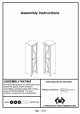
Assembly Instructions ASSEMBLY RATING Tools Required for Assembly: The Assembly Rating is a 5-point system that shows the degree of effort needed in assembling a specific product (with 1 being iri § Te easy and & being difficult, Formosa Philips Sorcerer ot studied) products, two persons are recommended.
90-DAY LIMITED REPLACEMENT PARTS WARRANTY This item comes with a 90-day limited replacement parts warranty to the original purchaser of new products against defects in materials and workmanship for a period of ninety (90) days from the date of receipt. This warranty 15 not transferable.
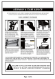
ASSEMBLY & CARE ADVICE FOR YOUR FURNITURE TO LAST, CORRECT ASSEMBLY AND PROPER MAINTENANCE ARE NECESSARY. PLEASE FOLLOW THE INFORMATION PROVIDED BELOW TO FULLY ENJOY YOUR FURNITURE. BASIC ASSEMBLY TECHNIQUES Hyde highly recommended halt assembly Should BE Dane nerd the arts of fs intended location. Make Sif yeu Have headlight Space To move arid during the assembly ALLAYS have 81 sas in people te Bast with reins porting And unblushing {hie protract ta avid any potential infancy landlord damage.
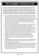
PER-ASSEMBLY INTRODUCTION Unless your are particularly adept at assembling flat-antiknock-down furniture ‘we understand building ready-to-assemble failure bean frustrating experience for some. To help avoid confusion and to make the assembly process quicker and smoother, we have provided some helpful tips. Before you begin the assembly.
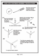
CAM LOCK FASTENER ASSEMBLY INSTRUCTIONS Note: Every cam lock bolt must have a sam lock connector in order to fasten the parts together, {1) Align the cam connector with its Secure the threaded i side opening {or arrow) end of the cam bolt pointing to the small busing a drilled hole. S screwdriver. Turn right (clockwise) to tighten, Two parts should fit snugly 3) against each other. Insert the cam lock bolt into the per-drilled hole above the cam connector.
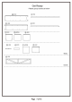
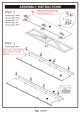
ASSEMBLY INSTRUCTIONS STEP : 1 Hardware (T) x PCS Hardware (3) x PCS Hardware (4) x PCS D2 Attach stopper (£4) onto panel (FIN.
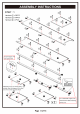
ASSEMBLY INSTRUCTIONS STE p . 2 Align hinges (#5) to panel then. secure by using screws (#63.
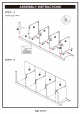
ASSEMBLY INSTRUCTIONS it stoppers (#4) are placed on the left side facing If stoppers (#4) are placed on the right side the anti, farrow this image. fating the unit, follow this image. Hardware (8) x PCS Align binges on panel (#K} to the unit, then secure by using screws STEP: 9 Hardware 0 x 8 PCS Hardware {J x 8 PCS (Bs Align and insert fixative plates (#10) all around the grooves of the back panels, then secure by using resews Fl 1.
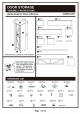
ASSEMBLY INSTRUCTIONS STEP: 10 Hardware {3 x 1PC Hardware 65 x 1PC Hardware {8 x 1PC Hardware 3) x 1PC Hardware {8 x 2PC8 Hardware 9 x 1PC 23 Align bracket (#17) to the top back of the unit, then secure by using screws Use strap (#19) onto the bracket (#17) and hook 13 Measure and drill a hole into the wall according to the height of the unit.
ASSEMBLY INSTRUCTIONS STEP : 11 PX tightened. ASSEMBLY i5 COMPLETED ~ JF Make sure the unit is rested on a flat surface and does not feel loose or wobbly.