
Installation Guide


1
INTRODUCTION
This macerator is manufactured in a factory which is quality
certified to ISO 9001 (2000) accredited by AFAQ.This
equipment benefits from the latest technological innovations
concerning soundproofing.To benefit fully from the advantages
provided by this new generation of appliances, it is important
to comply with the installation instructions.
1.1 - GENERAL DESCRIPTION
The macerating unit is a residential pumping system for
toilet and bathroom fixtures. The system is comprised of three
major components :
- the macerating unit, which connects to the outlet of
a rear spigot outlet toilet
- The toilet bowl
- The toilet tank
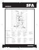
The macerating unit also consists of three major parts: the
container which houses the operating mechanism; a pressure
chamber which automatically activates and deactivates; the
induction motor which drives the cutting blade and the impeller.
The macerating unit can simultaneously receive wastewater
from several sanitary fixtures, e.g. sink, shower, bathtub,
urinal, but only one water closet per unit.
Macerating units are designed for the disposal of human
waste, toilet paper and water. They are not intended to be
used for the disposal of kitchen waste, neither are they
intended to be used for the disposal of waste water from such
pump appliances as dishwashers and clothes washers.
Macerating system must discharge into a minimum 3/4-inch
sanitary drainage pipe. The macerating system will pump up
to 15 feet vertically, with a
1
/4" per foot gravity fall (minimum)
constantly throughout the horizontal run to the point of dis-
charge. If you require a vertical lift it should precede any “hori-
zontal” run and should commence as near as possible to the
discharge elbow. Once you have started the horizontal run,
you cannot change directions in a upward vertical manner.
SANITARY INLETS
The macerating unit is equipped with two additional 2" inlets,
one on either side of the case. These inlets, which incorporate
an internal check valve, are used to connect the drainpipe of
other sanitary fixtures to the macerating unit.
Note: In case one of the inlets is not used by a fixture, you will
need to block off this inlet with the plugs provided.
BATHTUB
Any regular bathtub can be used, as only the drainpipe
connects to the macerating unit. When installing a
bathtub, we recommend to build a platform out of
2 x 8-inch lumber, on which the tub is placed. This gives
enough space for a p-trap and slope toward the
wastewater inlets.
SHOWER STALL
When installing a shower, a special raised shower base
can be installed. This eliminates the building of a
platform. Alternatively, you may want to purchase a
regular shower and also build a platform for it. We
recommend to build a platform out of 2 x 8-inch lumber.
Note: Platform height. The actual distance between
the p-trap of the additional fixture and the macerating
unit determines the necessary clearance to install the
p-trap and elevation required to ensure a minimum
gravity flow of
1
/4-inch per foot.
1.2 - NORMAL OPERATING CYCLE
As the flush is operated or as the bath, shower and lavatory
discharge, the water and waste enter the unit and the water
level begins to rise, triggering the micro-switch in the pressure
chamber. This in turn activates the motor. The shredded waste
is picked up by the impeller and discharged through a
3
/4" or
1" outlet pipe to a sanitary sewer or soil stack.
Safety note: For safety the macerating unit should never be
activated with the lid removed.
2
INSTALLATION
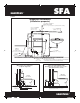
2.1 - PREPARING THE MACERATING UNIT
The plastic discharge elbow/check valve assembly should be
inserted (long end) into the rubber hose located on the top of
the lid. The step-down rubber fitting should then be inserted at
the discharge side of the elbow assembly and secured with the
provided metal clamps. The step-down rubber fitting may need
to be cut depending on the discharge pipe diameter. Three
metal clamps should be used to secure all fittings.
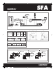
2.2 - CONNECTION OF THE OTHER SANITARY
APPLIANCES
Saniplus : See page 3 drawing 7c
• To connect to the side entries of the case, use the side
connector. Secure with clamps.
• Plug the unused inlet with blanking plug after greasing the
joint.
Warning: Ensure when connecting a shower to the macerating
unit that the underside of the shower tray is raised by at least
7 inches from the floor.
2.3 - WATER CLOSET ASSEMBLY
The tank comes with the fill and flush valve assembled,
however, please ensure that all screws, nuts, etc. are tightened
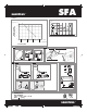
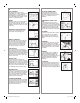
2.4 - SYSTEM ASSEMBLY
Saniplus : See page 3 drawing 7a
1. Place the macerating unit in the desired spot and connect
all inlet and outlet waste piping to the unit. (See Connection
to discharge pipe work).
2. Place the spigot outlet of the toilet bowl firmly against the
white accordion connector and mark the floor through the
holes in the bowl.
3. Remove bowl and bore two holes approximately 2
1/4" deep
with a
5/16" masonry drill bit. Insert plastic plugs into holes.
If the floor is wood, bore a pilot hole with a
1/4" drill bit.
4. Place the bowl in front of the macerating unit and pull the
accordion gasket all the way onto the rear spigot outlet. Attach
with supplied gear clamp. Check that gasket and clamp are
even all around.
5. Move the bowl over the holes in floor. Slip the plastic china
protectors over the lag screws.Tighten lag screws (do not over
tighten) and snap plastic cover caps in place.
6. Locate the tank to bowl kit and place foam gasket on the
spud of the flush valve and over nut. Place tank on top of the
bowl. Insert screws and gasket through the tank and tighten nuts
underneath. Do not overtighten as this may damage the china.
The system is supplied with fixing lugs to prevent it from
moving during use. To optimize the latest technical
developments concerning soundproofing incorporated into this
unit,it is important to:
• position the WC pan so that it is not in contact with a partition
or wall of the room.
• place the WC pan on a perfectly level surface to ensure that
the resilient mounts are fully efficient.
• fix the discharge pipe correctly with distances of not more
than 3ft (1m) between the fastenings.
2.5 - CONNECTION TO WATER SUPPLY
Connect the water supply hose to the fill valve.
2.6 - CONNECTION TO THE DISCHARGE PIPE WORK
These macerating units have an elbow, and a «step-down»
bushing simply cut off the appropriate portion of the bushing
in order to fit it to the discharge pipe. Use ridged wall pipe, not
flexible pipe or hose, as flexible pipe may distort over time. Use
3/4" or 1" discharge pipe.
Install a “full-port” ball or gate valve and a union in the
discharge pipe in order to facilitate the removal of the
macerating unit. Place the union or hose connector then the
valve at the lower portion of the discharge pipe.
If you wish the unit to pump vertically and horizontally you may
calculate that 3 feet of vertical lift is equivalent to 30 feet of
“horizontal” run.
8452 229 SANIPLUS USA Notice.indd 6 5/01/10 12:02:17