BSB 60 Back-Pack Leaf Blower PLEASE KEEP THIS MANUAL IN A SAFE PLACE
Contents 1. Guide to using this manual………………………………………....1 2. Safety precautions………………………………………………… .2 3. Maintenance and repair…………………………………………......6 4.Technical specifications…………………………………….…….…7 5. Parts list.…………………………………………………...….….....8 6. Assembling the unit……….………………………………..…….....8 7. Fueling……………………………………………………..….…....9 8. Starting/Stopping…………………………………………….….…11 9. Operating instructions………………………………………….….13 10. After finishing work…………………………………………..….13 11.Storing the machine………………………………………….
Guide to Using this Manual Pictograms All the pictograms attached to the machine are shown and explained in this manual. The operating and handling instructinns are supported by illustrations. Symbols in text The individual steps or procedures described in the manual may be marked in different ways: Step or procedure without direct reference to an illustration. Description of step or procedure that refers directly to the illustration and contains item numbers that appear in the illustration.
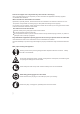
Careless or improper use of any blower may cause serious or fatal injury. Have your dealer show you how to operate your blow et.Observe all applicable local safety regulations,standards and ordinances. Minors should never be allowed to use a blower. Bystanders, especially children, and animals should not be allowed in the area where a blower is in use. The operator is responsible for avoiding injury to third parties and damage to their property. Do not lend or rent your blower without the owner's manual.
Always shut off the engine before fefueling. Gasoline is an extremely flammable fuel. Do not smoke or bring any fire or flame near the fuel. Do not fuel a hot engine - fuel may spill and cause a fire. Remove the fuel filler cap on the unit carefully so as to allow any pressure build-up in the tank to release slowly. Fuel your blower, in well-ventilated areas, outdoors only. Wipe off any spilled fuel before starting and check for leakage. Take care not to get fuel on your clothing.
During operation Warning! Your blower produces toxic exhaust fumes as soon as the engine is running. These gases (e.g. carbon monoxide ) may be colorless and odorless. To reduce the risk of serious or fatal injury from breathing toxic fumes, never run the blower indoors or in poorly ventilated locations. Ensure proper ventilation when working in trenches, hollows or other confined areas.
- Hand protection (wearing warm gloves) - breaks The period of usage is shortened by: - Any personal tendency to suffer from poor circultaion (symptoms: frequently cold fingers, itching). - Low outside temperatures. - Gripping force (a tight grip hinders circulation). Continual and regular users should monitor closely the condition of their hands and fingers. If any of the above symptoms appear, seek medical advice.
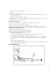
Mounting the spraying attachment Push the extension tube into the pleated hose as far as it will go. Rotate the tube to the left (counter-clockwise) as far as stop and leave it in that position until you have completed the following adjustments. Turn the control handle counterclockwise to the horizontal position. Now rotate the extension rube counterclockwise until the metering unit points in the same direction as the control handle. Tighten down clamp screw (see "Adjusting the control handle").
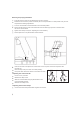
Fuel Your engine requires a mixture of gasoline and engine oil. The quality of these constituents and the mix ratio have a decisive influence on the function and scervice life of the engine. Loosening the harness straps Lift the tabs of the two sliding adjusters. Adjust the straps so that the backplate is held firmly and comfortably against your back. Unsuitable fuels or lubricants or mix ratios other than those specified may result in serious damage to the engine (piston seizure,rapid rate of wear, etc.
Before fueling, clean the filler cap and the area a around it to ensure that no dirt falls into the tank. Position the unit so that the filler cap is facing up. Take care not to spill fuel while fueling and do not overfill the tank. After fueling, tighten down filler cap by hand as securely as possible. Change the fuel pickup body once every year Drain the fuel tank. Use a hook to pull the fuel pickup body out of the tank and take it off the hose. Push the new pickup body into the hose.
Observe safety precautions - see chapter" Safety Precautions". Slide the stop switch (1) to ON Move the setting lever (2) to the center position - this is the starting throttle position Note: The setting lever can be used to select any throttle opening between idle speed (lower stop) and full throttle (upper stop). Set the lever to idle position before switching off the engine.
Guide it slowly back into the housing so that the starter rope can rewind properly. When engine begins to fire: If engine is cold: Turn choke knob to engine runs. and continue cranking until If engine is warm: Continue cranking until engine runs. As soon as engine runs: Move the setting lever (2) to the lower stop so that the engine settles down to idle speed.
Set the stop switch to OFF Open the throttle fully. Pull the starter rope several times to clear the combustion chamber. Fit the spark plug and reconnect the spark plug boot. Move the stop switch to ON Turn the choke knob to even if the engine is cold. Now start the engine. Fuel tank run until dry and then refueled Pull the starter rope several times to prime the fuel line.
Dirty air filers reduce engine power increase fuel consumption and make starting more difficult. If there is a noticeable loss of engine power Turn choke knob to Release the screws (1) and pull off the filter cover (2). Remove the filter from the cover and inspect it - if it is dirty or damaged, clean the filter or fit a new one. Install the main filter and prefilter elements in the filter cover. Fit the cover on the filter base and tighten it down firmly.
Fine Tuning for Operation at High Altitude A slight correction of the setting may be necessary if engine power is not satisfactory when operating at high altitude: check the standard setting. Warm up the engine. Turn the high speed screw (H) slightly clockwise (leaner). On models with limiter caps, turn high speed screw (H) 1/4 turn, but no further than stop. If the setting is too lean there is a risk of engine damage due to insufficient lubrication and overhe ating.
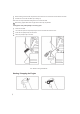
If the spark plug comes with a detachable adapter nut (1), screw it on fi rm ly. On all spark plugs: Always press the boot (2) firmly on to the spark plug (3). Engine Running Behavior If engine running behavior is unsatisfactory even though the air filter is clean and the carburetor properly adjusted, the cause may be in the muffler. Have the muffler checked for contamination (coking) by dealer. Replacing Starter Rope and Rewind Spring 1 1 2 1 Replacing the starter rope Remove the screws (1).
Remove the spring clip (3). Remove the rope rotor with washer (4) and pawl (5). Ease the cap (6) out of the starter grip. Remove remaining rope from the rotor and grip. Tie a simple overhand knot in the end of the new starter rope (see Specifications) and then thread the rope through the top of the grip and the rope bush (7). Refit the cap in the grip. Thread the rope through the rotor and secure it in the rotor with a simple overhand knot.
Make a loop in the unwound starter rope and use it to turn the rope rotor six full revolutions in the direction of the arrow (see illustration). Hold the rotor steady -.straighten the twisted rope. Release the rotor and let go of rope slowly so that it winds onto the rotor. The starter grip must sit firmly in the rope guide bush. lf the grip droops to one side: lncrease spring tension by one additional turn.
Minimize Wear and Avoid Damage Observing the instructions in this manual helps reduce the risk of unnecessary wear and damage to the power tool. The power tool must be operated, maintained and stored with the due care and attention described in this owner's manual. The user is responsible for all damage caused by non-observance of the safety precautions, operating and maintenance instructions in this manual. This includes in particular: - Alterations or modifications to the product not approved by dealer.
Specifications Ignition System Single cylinder two-stroke engine Type: Displacement: 56.5 cm3 Bore: 46 mm Stroke: 34 mm Idle speed: 2.800 rpm Engine power: 2.5 kw Spark Plug (suppressed) : Weight: 10.5 kg Ari flow rate: 1060 m /h Electrode gap: Spark plug thread: 3 Spraying attachment Fuel System Container capacity: 141 Size of filler strainer 1 mm mesh: Discharge rate 0.14-3.03 l/min (infinitely) variable) Quantity left in 0.
IE46F-3 GASOLINE ENGINE EXPLOSIVE PICTURE
1E46F-3 GASOLINE ENGINE Ser.No.Erp No. Part Name Qty Ser.No. Erp No . Part Name Qty Ser.No . Erp No. Part Name Qty Ser.No.Erp No.
BSB60 EXPLOSIVE PICTURE OF FRAME AND SPRAYING
BSB 60 SPARE PARTS LIST OF IMPLEMENT PICTURE Ser.No. Erp No. Part Name Qty Ser.No. Erp No. Part Name Qty Ser.No. Erp No. Part Name Qty Ser.No. Erp No. Part Name Qty 2-1 1826 BELT ASS'Y 2 2-16 6982 RIGHT FRAME 1 2-31 7657 LONG JOINT TUBE 1 2-46 2-2 4450 SCREW M6X12 2 2-17 6981 LEFT FRAME 1 2-32 4318 SCREW ST2.
EC DECLARATION OF CONFORMITY Fujian Jinjiang Sanli Engine Co., Ltd. Declares that the following equipment manufactured by Fujian Jinjiang Sanli Engine Co., Ltd conforms to the following Directive(s):2000/14/EC,2006/42/EC,2004/108/EC and 97/68/EC of the European Parliament and of the council on the approximation of the laws of the Member States relating to the noise emission in the environment by equipment for use outdoors.
Notes
BSB 60 Address
WARRANTY CARD REGISTER YOUR MACHINE TO VALIDATE YOUR WARRANTY. To validate your warranty, register your equipment with SANLI after its purchase by returning the warranty card provided at the back of the user's manual or on the website www.sanli.co.uk/register,www.sanli.fr,www.sanli.com.