
Use and Care Guide
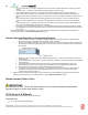


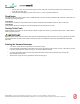
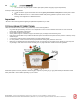

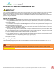
Table Of Contents
- TOC-Important-Installation-Guidelines
- TOC-Model-Differences
- TOC-Check-Contents-of-Box
- TOC-Do-Not-Remove-Paper-Mat
- TOC-Important-Notices
- TOC-Ready-to-Go-
- TOC-90-Bends-in-Vent
- TOC-1.-Position-Toilet
- TOC-1
- TOC-2.-Cut-Vent-Hole-in-Roof-Ceiling
- TOC-2
- TOC-3.-Vent-Roof-Stack-Installation
- TOC-3
- TOC-4.-Insert-Vent-Pipe-into-System
- TOC-4
- TOC-5.-Attach-Union-Coupling-Optional-
- TOC-5
- TOC-6.-Connect-Remaining-Vent-Pipe
- TOC-7.-Install-Drain
- TOC-8.-Seal-All-Vent-Connections
- TOC-9.-Insulate-Exposed-Pipe
- TOC-6
- TOC-10.-Attach-Rain-Cap-or-Wind-Turbine
- TOC-Protect-from-the-Elements
- TOC-Install-Rigid-Vent-Pipe-not-supplie
- TOC-Connect-Flexible-Vent-and-Rigid-Pip
- TOC-Attach-Wind-Turbine-Ventilator-
- TOC-Seal-All-Vent-Connections
- TOC-Install-Vacuum-Toilet
- TOC-Install-Drain
- TOC-Connect-Three-Components-of-System
- TOC-Start-Here
- TOC-Position-the-System
- TOC-Connect-Vacuum-Toilet-to-Vacuum-Gen
- TOC-Connect-Vacuum-Generator-to-Compost
- TOC-Fasten-Vacuum-Generator-Unit-and-Co
- TOC-Connect-Vacuum-Generator-to-12v-Pow
- TOC-Connect-Composting-System-to-AC-Ele
- TOC-Plug-Play-Wiring-Connection
- TOC_Do_Not_Add__3175881415145758
- TOC_Rated_Capacity_4164048674046512
- TOC_Operation_is_Easy_8826685531918387
- 1_System_Operation_09638061436967571
- TOC_1_Initial_System_Start_Up_1095042459
- TOC-1.-Initial-System-Start-Up
- TOC_2_Power_Control_42472747931111743
- TOC-2.-Power-Control
- Non_Electric_SystemsNot_applic_933833838
- FlushSmart_VF_models_Always_tu_554945394
- TOC_12VDC_Systems_12964841970897056
- TOC-12VDC-Systems
- FlushSmart_VF_models_Always_tu
- 5_Weekly_Operation_5923775715714038
- TOC-Typical-Emptying-Times
- TOC-Indications-of-Emptying-Required
- TOC-Before-you-Empty
- TOC_Introduction_3353822634090_525738961
- Proper_System_Operation_1312612757753413
- TOC_Outside_Odour_901114465392_444162368

Use as directed. To ensure proper performance, please be sure to contact us if you have installation or operation questions.
ENVIROLET®/SG INSTALLATION & OPERATION MANUAL (7MINS11D 12.15) • Envirolet® is a registered trademark. ©2016, Sancor Industries Ltd.
42
o “A - Above Floor Rear” - Connects to fitting at back of vacuum toilet in VF300 models and to cup fitting in VF700
models.
o “B - Below Floor” - Connects to included floor flange fitting below the bathroom floor.
o Apply included lubricant to inside of 1.5” flex drain hose and outside fittings to allow for easier connection.
o Use 2 x Gear Clamps for tight fit. It is essential that 2 be used. Each Gear Clamp should be installed with the
tightening-screw directly opposite the other (12 o’clock and 6 o’clock) to ensure tight connection and proper vacuum
seal.
o Place opposite end of 1.5”/38mm drain hose through bathroom wall (or floor) for “A” and “S” models in order to
connect to Vacuum Generator Unit. “B” models are already below floor ready to connect to Vacuum Generator
Unit.
o Connect opposite end of 1.5”/38mm drain hose to Vacuum Generator Unit drain inlet. Apply included lubricant to
drain hose and outside fittings to allow for easier connection.
o Once again, use 2 x Gear Clamps for tight fit. It is essential that 2 are used. Each Gear Clamp should be installed
with the tightening-screw directly opposite the other (12 o’clock and 6 o’clock) to ensure tight connection and proper
vacuum seal.
• Make sure all connections are sealed tight. Vacuum toilet and Vacuum Generator should ideally not exceed maximum
recommended distance. Refer to Maximum Distances section.
Connect Vacuum Generator to Composting System
a. Insert small end of 1.5”/38mm white plastic reducer coupling inside 1.5”/38mm drain hose. Apply included
lubricant to drain hose and outside fittings to allow for easier connection.
b. Use 2 x Gear Clamps to seal tightly. It is essential that 2 are used. Each Gear Clamp should be installed with
the tightening-screw directly opposite the other (12 o’clock and 6 o’clock) to ensure tight connection and proper
vacuum seal.
c. Select left, right or top drain entry on Envirolet®/SG Composting Unit. This is where the drain hose will enter
composting unit.
d. Connect white plastic coupling end of 1.5”/38mm drain hose to selected 1.5”/38mm drain inlet on Envirolet®/SG
Composting Unit.
e. Secure coupling with silicone or PVC solvent to ensure proper seal (and prevent liquid or odour leak).
f. Ensure drain cap covers are secured tightly on unused drain inlets on Envirolet®/SG Composting Unit.
g. Connect other end of drain hose to Vacuum Generator Unit drain pump outlet.
h. Once again, use 2 x Gear Clamps for tight fit. It is essential that 2 are used. Each Gear Clamp should be
installed with the tightening-screw directly opposite the other (12 o’clock and 6 o’clock) to ensure tight
connection and proper vacuum seal.
2. Make sure all connections are sealed tight. Vacuum Generator and Envirolet®/SG Composting Unit should should
ideally not exceed maximum recommended distance. Refer to Maximum Distances section.
Fasten Vacuum Toilet to Floor
IMPORTANT
All FlushSmart VF 300, 700 and 800 Series toilets must be connected with the included Water
Regulator Supply to control water volume in toilet.
VF700 Series A & B Models
VF700 Series models feature an electronic push-button flush.
VF700 A & B Series
Ø “A” - Above Floor Rear (straight fitting)
or