e00_l8had_us_7.
e00_l8had_us_7.book Page 1 Wednesday, March 10, 2004 2:47 PM PRECAUTION Declaration of Conformity CAUTION Model Number Trade Name Responsible party Address : DSR-300 : SANYO : SANYO FISHER COMPANY : 21605 Plummer Street, Chatsworth, California 91311 Telephone No. : (818) 998-7322 z This device complies with Part 15 of the FCC Rules.
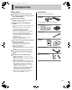
e00_l8had_us_7.book Page 2 Wednesday, March 10, 2004 2:47 PM INTRODUCTION Main features Accessories This digital video recorder can be used to store images recorded by monitoring cameras onto a removable HDD. Check that you have all the parts below. Power cord AC adapter Supports removable HDDs This feature allows you to remove and store HDDs containing important recordings. * Do not use the AC adapter with other equipment.
e00_l8had_us_7.book Page 3 Wednesday, March 10, 2004 2:47 PM INTRODUCTION Symbols used in this manual Information describing operation methods or how to get the most out of functions. Information describing the correct use of the digital video recorder. (→P. xx) indicates the page to be referred to. Copyright z This manual and software are copyrighted by Sanyo Electric Co., Ltd. z Brand and product names used in this manual are the trademarks or registered trademarks of their respective companies.
e00_l8had_us_7.book Page 4 Wednesday, March 10, 2004 2:47 PM CONTENTS 1 BEFORE USE .................................................8 2 REPLACING A REMOVABLE HDD ............ 10 Notes on handling removable HDDs ...............8 Conditions to avoid .........................................8 The hard disk and cooling fan are expendable items ...............................................................8 Installation conditions ......................................8 For important recordings ............
e00_l8had_us_7.book Page 5 Wednesday, March 10, 2004 2:47 PM CONTENTS SETTINGS MENU CONFIGURATION AND OPERATIONS ..............................................42 SETTINGS 1 DISPLAY/VIDEO LOSS SET ....................... 68 Displaying menu screens and setting screens .........................................................42 To restore menu setting items to their default values ................................................43 Overview of sub-menus .......
e00_l8had_us_7.book Page 6 Wednesday, March 10, 2004 2:47 PM CONTENTS INTRODUCTION INTERFACE SPECIFICATIONS 1 INTERFACE SPECIFICATIONS (when optional interface board is installed) .....81 OPERATION RS-232C .......................................................81 RS-485 ..........................................................81 Setting the RS-485 termination switch ..........82 Commands ....................................................83 Commands (RS-485 only) ............................
e00_l8had_us_7.book Page 7 Wednesday, March 10, 2004 2:47 PM CONTENTS NETWORK OPERATION 1 RECORDING IMAGES (when optional interface board is installed) .....112 4 OPERATIONS IN SEARCH MODES (when optional interface board is installed)..... 119 Normal recording ........................................112 Timer recording ...........................................112 Alarm recording ...........................................112 Pre-alarm recording ....................................112 1.
e00_l8had_us_7.book Page 8 Wednesday, March 10, 2004 2:47 PM 1 BEFORE USE Notes on handling removable HDDs This unit uses removable hard disk drives (HDD). Be sure to observe the following points carefully when operating, setting-up and servicing the unit. Do not subject the unit to shocks or vibration.
e00_l8had_us_7.book Page 9 Wednesday, March 10, 2004 2:47 PM 1 BEFORE USE Hard disk protection The hard disk is checked automatically at power ON. If a hard disk problem is found, the CHANGE DISK indicator flashes. To initialize the disk or save images stored on the disk, contact a Sanyo service centre. Care z To clean the digital video recorder, unplug the power plug from the wall outlet and wipe the unit lightly with a soft cloth.
e05_l8had_us_7.fm Page 10 Thursday, March 11, 2004 3:03 PM 2 REPLACING A REMOVABLE HDD 2 z When replacing with a HDD used in a DSR-300; Of the menu settings, only the recording area settings and the overwrite on/off setting are used for the HDD. z When replacing with a HDD used in a DVR other than a DSR-300; It is treated as a new HDD. The recorded contents will be initialized. z About the HDD; Install an HDD provided by Sanyo.
e00_l8had_us_7.book Page 11 Wednesday, March 10, 2004 2:47 PM 2 5 REPLACING A REMOVABLE HDD Insert the tray release key, turn it in the direction of the arrow, and then press the [CHANGE DISK] button. Removal 1 The HDD indicator will light up and the CHANGE DISK indicator will switch from green to red. With the power turned on, press and hold the [CHANGE DISK] button for at least 2 seconds. The CHANGE DISK indicator changes from red to flashing green, then lights steadily after 10 seconds.
e00_l8had_us_7.book Page 12 Wednesday, March 10, 2004 2:47 PM 2 3 REPLACING A REMOVABLE HDD Pull the HDD tray out using the handle. INTRODUCTION Pulling the handle causes the HDD tray lock to be released. 4 5 Pull the clasp, release the lock, and remove the cover. Remove the 4 screws, take the removable HDD out of the tray, and release the connector. z Whenever the unit is to be transported, ensure that the HDD tray is removed from the unit and packaged separately.
e00_l8had_us_7.book Page 13 Wednesday, March 10, 2004 2:47 PM 3 NAMES AND FUNCTIONS OF PARTS Front panel 1 2 3 10 11 5 4 12 13 14 15 16 17 18 19 20 21 7 8 9 22 23 24 1. [STILL] button Pauses the screen image when pressed during playback. Pressing the button again restarts playback. 11. [ALARM] button (JP. 30) When the [ ] or [ ] button is pressed during playback, the unit skips to the next earlier or later alarm. 2.
e00_l8had_us_7.book Page 14 Wednesday, March 10, 2004 2:47 PM 3 NAMES AND FUNCTIONS OF PARTS INTRODUCTION 17. [ ] button Used to move the cursor in menu screens up. Also used to change setting values. Used for frame advance (forward) and adjusting the CUE/ REVIEW speed. 18. [CUE/ENTER] button When pressed during playback, lets you fast-forward the image while watching it on-screen. When pressed while the image is still, forward playback is performed. Also used for menu screen operations. 19.
e05_l8had_us_7.fm Page 15 Friday, March 12, 2004 9:46 AM 3 NAMES AND FUNCTIONS OF PARTS Rear panel 1 2 3 A RS485 B RS232C DC IN 4 IN AUDIO OUT ALARM NON-REC REMOTE IN 5 6 RS485 TERMINATE OFF ON LAN VIDEO LOOP OUT CLOCK WARNING ALARM 7 OUT ALL RESET SERIES SW COM IN RESET OUT OUT COM IN OUT OUT FULL FULL COM IN OUT OUT COM 8 9 10 11 12 14 15 16 1. Fan 15. VIDEO OUT terminal 2. RS-232C terminal (when option board is installed) 16. Control and alarm terminals 3.
e00_l8had_us_7.book Page 16 Wednesday, March 10, 2004 2:47 PM 4 INSTALLATION AND CONNECTIONS INTRODUCTION This section describes how to connect the digital video recorder to the CCTV camera and other devices. Be sure to read the instruction manuals for each connected device. Improper connections can cause smoke or malfunctions. Basic connections The connections for the camera, TV monitor, system controller, multiplexer, microphone, and PC are shown below.
e00_l8had_us_7.
e00_l8had_us_7.book Page 18 Wednesday, March 10, 2004 2:47 PM 4 INSTALLATION AND CONNECTIONS 1 z If the CHANGE DISK indicator is flashing in red The digital video recorder has a self-check function that indicates problems. If there is a problem at power ON or during operation, the type of problem is indicated by how rapidly the CHANGE DISK indicator flashes. Contact a Sanyo Authorized Service Centre if the CHANGE DISK indicator flashes.
e00_l8had_us_7.book Page 19 Wednesday, March 10, 2004 2:47 PM 1 PREPARING FOR USE (5) Alarm display and alarm count display (JP. 24) When you set an alarm using the “ALARM REC MODE SET” menu item, the alarm display area displays the following information. z When alarm recording is set; “ALARM” is displayed. “ALARM” is flashed during alarm recording. z When pre-alarm recording is set; “PRE” is displayed. When an alarm occurs, “PRE” disappears, “ALARM” is displayed, and the number of alarms is shown.
e00_l8had_us_7.book Page 20 Wednesday, March 10, 2004 2:47 PM 1 PREPARING FOR USE Changing the position of the operation display area [A] [B] [EXIT/OSD] button [C] OPERATION [A] Normal recording area 1 Recording mode Press the [EXIT/OSD] button repeatedly. Pressing the [EXIT/OSD] button repeatedly lets you move or erase the operation display area.
e00_l8had_us_7.book Page 21 Wednesday, March 10, 2004 2:47 PM 2 SETTING THE LANGUAGE/CLOCK [ ] button [MENU] button [ [ ] button ] button [EXIT/OSD] button 2 This section describes how to set the language displayed on the monitor and how to set the digital video recorder’s internal clock. The screen is displayed with the cursor positioned on “ENGLISH”. [Settings] ( indicates default setting.
e00_l8had_us_7.book Page 22 Wednesday, March 10, 2004 2:47 PM 2 SETTING THE LANGUAGE/CLOCK 4 Setting the time Press the [ ] button. “01” (indicating the month) flashes. (Default setting: 01-01-2004 THU 00:00:00) Be sure to set the correct date and time. The digital video recorder stores the times of recordings for use in operations such as playback and search/playback. 5 Example: Setting May 20, 2004, 8:30 Press the [MENU] button. ] or [ ] button to select OPERATION 1 Press the [ “05”.
e00_l8had_us_7.book Page 23 Wednesday, March 10, 2004 2:47 PM 3 NORMAL RECORDING/TIMER RECORDING [REC/STOP] button [TIMER] button FULL indicator TIMER indicator Normal recording Timer recording Follow the procedures below to record the monitored image in the normal recording area. Follow the procedures below to record the monitored image in the normal recording area at the set time. 1 1 Press the [REC/STOP] button. The REC/STOP indicator lights. “ ” appears on the screen (i.e.
e00_l8had_us_7.book Page 24 Wednesday, March 10, 2004 2:47 PM 4 ALARM AND PRE-ALARM RECORDING ALARM FULL indicator ALARM indicator FULL indicator OPERATION [EXIT/OSD] button extended counting from that moment. The new alarm is not counted. z The latest 9,999 alarms are displayed in the alarm history (recording list). (Although the history can record up to 16,000 items, only 9,999 of these can be displayed on-screen.) z The panel’s ALARM indicator flashes.
e00_l8had_us_7.book Page 25 Wednesday, March 10, 2004 2:47 PM 4 ALARM AND PRE-ALARM RECORDING Pre-alarm recording If an alarm is detected Pre-alarm recording is automatically ended and alarm recording starts. z “PRE” from the operation display area is replaced by “ALARM” and the ALARM indicator flashes. Follow the procedures below to have the digital video recorder record an image from before detection of an alarm and the start of alarm recording. 1 Set pre-alarm recording.
e00_l8had_us_7.book Page 26 Wednesday, March 10, 2004 2:47 PM 5 NORMAL RECORDING/TIMER RECORDING PLAYBACK Follow the procedures below to playback images stored in the normal recording area (by normal recording or timer recording). Normal recording area [PLAY/STOP] button ] button [ ] button [ ] button [ Playback 1 ] button Fast-forward playback/fast-rewind playback Press the [PLAY/STOP] button. During playback, press the [ ] or [ ] button.
e00_l8had_us_7.book Page 27 Wednesday, March 10, 2004 2:47 PM 5 NORMAL RECORDING/TIMER RECORDING PLAYBACK Viewing still images Slow playback or fast-forward During playback, press the [ ] or [ ] button. The speed changes by one increment/decrement each time you press the button. [STILL] button Slow reverse playback or fast-rewind During reverse playback, press the [ ] or [ ] button. The speed changes by one increment/decrement each time you press the button.
e06_l8had_us_7.fm Page 28 Thursday, March 11, 2004 3:36 PM 5 NORMAL RECORDING/TIMER RECORDING PLAYBACK 3 Playback with a channel specified for the camera image Press the [ ] button. “ ” appears in the operation display area and the images from the specified channel are played back.
e00_l8had_us_7.book Page 29 Wednesday, March 10, 2004 2:47 PM 6 SEARCHING FOR RECORDED IMAGES (2) ALARM THUMBNAIL SEARCH (JP. 31) Lets you search and play back alarm images using thumbnails. Images stored in the alarm recording area or archive area can be located by searching and then played back. Five different search methods are available. Archive area 0016 0015 0014 0013 0012 0011 0010 0009 0008 Alarm recording area (3) TIME/DATE SEARCH (JP.
e00_l8had_us_7.book Page 30 Wednesday, March 10, 2004 2:47 PM 6 SEARCHING FOR RECORDED IMAGES 3 ALARM SEARCH Lets you search and play back all the alarm images stored in the alarm recording area. If pre-alarm images are being recorded, playback will start from immediately before the alarm. [SEARCH] button [ ] button [ ] button 1 [ The selected alarm image is displayed in the preview screen. You can display up to 8 alarm images. z To display the next (previous) image Press the [ ] or [ ] button.
e00_l8had_us_7.book Page 31 Wednesday, March 10, 2004 2:47 PM 6 SEARCHING FOR RECORDED IMAGES 5 ALARM THUMBNAIL SEARCH The selected image is played back on the entire screen. All alarm images stored in the alarm recording area can be displayed as thumbnails. [SEARCH] button [ ] button [ Press the [ ] button. ] button z In the same way as for alarm searching, playback is only possible within each alarm recording. Play the previous or subsequent alarm image using the [ALARM] button.
e00_l8had_us_7.book Page 32 Wednesday, March 10, 2004 2:47 PM 6 3 SEARCHING FOR RECORDED IMAGES Press the [ ] button. The cursor moves to “PREVIEW”. The
e00_l8had_us_7.book Page 33 Wednesday, March 10, 2004 2:47 PM 6 SEARCHING FOR RECORDED IMAGES ARCHIVE AREA SEARCH MOTION DETECTION SEARCH Follow the procedures below to playback images from the archive area. 1 By setting images recorded in the hard disk’s normal recording area (i.e.
e00_l8had_us_7.book Page 34 Wednesday, March 10, 2004 2:47 PM 6 4 SEARCHING FOR RECORDED IMAGES Press the [ ] or [ ] button to select the searching range, then press the [ ] button. (2) END: The date and time for the final screen stored in each recording area are displayed. (3) MOTION SENSOR: The motion sensor is displayed. (Example: Normal) The cursor moves to “CHANNEL”. (4) PREVIEW: The selected start time is displayed. 8 z When “NO USE” is set for “MULTIPLEXER” (JP. 52) in “2.
e00_l8had_us_7.book Page 35 Wednesday, March 10, 2004 2:47 PM 6 9 SEARCHING FOR RECORDED IMAGES Press the [ ] button. Viewing a motion sensor on-screen 1 The motion sensor setting screen is displayed. Motion sensors should be set at locations where movement is to be detected and viewed. See “Setting the motion sensor” (JP. 67) for details. 2 Press the [ “VIEW”. ] or [ ] button to select Press the [ ] button. Normal playback will be started for the specified image.
e00_l8had_us_7.book Page 36 Wednesday, March 10, 2004 2:47 PM 7 SAVING & COPYING RECORDED IMAGES Important images stored in the normal recording area or the alarm recording area can be copied to the unit’s archive area, a CompactFlash card, or a Microdrive. Copying an image to the hard disk’s archive area (JP.
e00_l8had_us_7.book Page 37 Wednesday, March 10, 2004 2:47 PM 7 SAVING & COPYING RECORDED IMAGES 7 Example: Copying a specified 10-minute image 3 Press the [ ] button, then the [ ] or [ ] button to select “MINUTES”. Press the [COPY] button. The copy setting screen appears. The cursor moves to “COPY TO”. [Settings] ( indicates default setting.) Setting PICTURES 4 Press the [ ] button, then the [ ] or [ ] button to set the copy destination to “ARCHIVE AREA”.
e00_l8had_us_7.book Page 38 Wednesday, March 10, 2004 2:47 PM 7 SAVING & COPYING RECORDED IMAGES 4 Copying an archive area image to a CompactFlash card or Microdrive Press the [ ] button, then the [ ] or [ ] button to set the copy number. Any value between 1 and 60 can be set. Copying to a Microdrive and to a CompactFlash card are carried out in the same way. 1 Insert the CompactFlash card. 5 6 Insertion method (2) (1) (1) Open the cover.
e06_l8had_us_7.fm Page 39 Thursday, March 11, 2004 3:38 PM 7 8 SAVING & COPYING RECORDED IMAGES Move the cursor to “START” and press the [ ] button. Recording area in CompactFlash cards When copied to the CompactFlash card, folders shown below are created and the images are stored within them. CompactFlash card SANYO 02032101 (1) Copying to the CompactFlash card starts. The message “COPY TO COMPACT FLASH!” is displayed on-screen. (2) When this has been completed, “COPY FINISHED!” is displayed.
e00_l8had_us_7.book Page 40 Wednesday, March 10, 2004 2:47 PM 8 SAVING MENU SETTINGS 2 Use the following procedure to save menu settings on a CompactFlash card or to load settings from a CompactFlash card back into the unit. These functions make it easy to use the same settings on a number of different digital video recorders. 1 Press the [ ] or [ ] button to select “YES”, then press the [ ] button. (1) The saving process begins.
e00_l8had_us_7.book Page 41 Wednesday, March 10, 2004 2:47 PM 8 2 SAVING MENU SETTINGS 3 Press the [ ] or [ ] button to select “YES”, then press the [ ] button. (1) The loading process begins. (2) When this process has been completed, “LOADING FINISHED!!” is displayed and the digital video recorder is restarted. Press the [ ] or [ ] button to select “LOAD MENUS FROM CF”, then press the [ ] button. The screen is displayed.
e00_l8had_us_7.book Page 42 Wednesday, March 10, 2004 2:47 PM MENU CONFIGURATION AND OPERATIONS This section describes the menu configuration, and which menu item to select for each operation. Moving to a sub-menu from MAIN MENU 1 or MAIN MENU 2 2 Displaying menu screens and setting screens [ ] button [ 1 ] button [ ] button to select a Cursor position ] button 3 [EXIT/OSD] button SETTINGS [ ] button ] or [ (Example: “3.
e00_l8had_us_7.book Page 43 Wednesday, March 10, 2004 2:47 PM MENU CONFIGURATION AND OPERATIONS Overview of submenus Entering settings in sub-menu screens Use the [ ], [ ], [ ] and [ ] buttons to change settings in setting screens. (2) (3) (1) The screens below are the sub-menus displayed by selecting items from the . Each time you press the [MENU] button, the sub-menus shown below will be displayed in the indicated order.
e00_l8had_us_7.book Page 44 Wednesday, March 10, 2004 2:47 PM MENU CONFIGURATION AND OPERATIONS (4) RECORDING CONDITIONS SET (JP. 56) Used to make settings when multiple units are connected together. In addition, this sub-menu also allows you to indicate whether recording is to be stopped or continued in overwrite mode when the available space for recorded data has been filled during recording. Overview of submenus (5) NORMAL REC MODE SET (JP.
e00_l8had_us_7.book Page 45 Wednesday, March 10, 2004 2:47 PM MENU CONFIGURATION AND OPERATIONS (4) SECURITY LOCK SET (JP. 72) Lets you set passwords to prevent unauthorized users from operating the digital video recorder. (5) NETWORK SET (JP. 76) Lets you make settings when connecting with PCs via a local-area network (LAN). Requires option board (sold separately). (6) HDD SET (JP. 79) Lets you initialize the hard disk. (7) POWER FAILURE/USED TIME (JP.
e00_l8had_us_7.book Page 46 Wednesday, March 10, 2004 2:47 PM MENU CONFIGURATION AND OPERATIONS Table of recording rate and times This unit’s recording time can be changed by modifying the recording rate and the recording picture quality. The following table provides reference values for picture quality and recording rate in a situation where images are field recorded and frame recorded to the normal recording area on this unit’s removable HDD.
e00_l8had_us_7.book Page 47 Wednesday, March 10, 2004 2:47 PM MENU CONFIGURATION AND OPERATIONS When recording with a 160-GB hard disk at 100% capacity Field recording Recording rate (fields per second) Recording time BASIC NORMAL ENHANCED FINE SUPER FINE 15kB 22kB 30kB 42kB 50kB 60.00 42H 30H 22H 16H 12H 30.00 85H 60H 45H 32H 24H 20.00 127H 90H 67H 49H 37H 15.00 170H 120H 90H 65H 49H 10.00 255H 180H 135H 98H 74H 7.50 340H 241H 180H 131H 99H 6.
e00_l8had_us_7.book Page 48 Wednesday, March 10, 2004 2:47 PM MENU CONFIGURATION AND OPERATIONS Recording time This table shows the recording times for pre-alarm recording. Refer to this table when setting pre-alarm recording. (JP. 66) Recording rate (fields per second) Recording time (s: seconds, m: minutes) 5s (5s) 10s (10s) 20s (20s) 40s (40s) 60s (1m) 120s (2m) 180s (3m) 240s (4m) 300s (5m) 600s (10m) 900s (15m) 20.00 15.00 10.00 7.50 6.00 5.00 4.29 3.75 3.33 3.00 2.73 2.31 2.00 1.67 1.
e00_l8had_us_7.book Page 49 Wednesday, March 10, 2004 2:47 PM 1 LANGUAGE/CLOCK SET 3 You can perform the following functions: z Change the language used to display on-screen information.* z Set the date and time displayed on the normal screen.* z Set the clock to adjust automatically for daylight savings time. z Set all the devices to the same time automatically when multiple devices are connected. *: See P. 21 for the corresponding procedure.
e00_l8had_us_7.book Page 50 Wednesday, March 10, 2004 2:47 PM 1 LANGUAGE/CLOCK SET 11 Press the [ ] or [ ] button to select the desired time, then press the [ ] button. When “USE” is selected for You can set the date/time at which the time is switched from standard time to daylight savings time, and the date/ time at which the time is switched back again. The cursor moves to the minutes portion of the time. Set the desired minutes in the same manner.
e00_l8had_us_7.book Page 51 Wednesday, March 10, 2004 2:47 PM 1 3 LANGUAGE/CLOCK SET Press the [ ] button. “01” flashes. 4 Press the [ ] or [ ] button to select the desired time, then press the [ ] button. Set the time 5 Press the [EXIT/OSD] button. The display returns to the normal screen. 6 Repeat procedures 2 to 5 to set the time on the second digital video recorder. When you have finished making the settings, the display returns to the normal screen.
e00_l8had_us_7.book Page 52 Wednesday, March 10, 2004 2:47 PM 2 VIDEO INPUT SET [ [MENU] button ] button [ ] button [ ] button [ [EXIT/OSD] button Press the [ ] or [ ] button to select the multiplexer to be used. SETTINGS 4 This section describes the settings to be made when using this unit in combination with a multiplexer (sold separately) and the settings for video input (analog). ] button [Settings] ( indicates default setting.
e00_l8had_us_7.book Page 53 Wednesday, March 10, 2004 2:47 PM 3 RECORDING AREA SET [ [MENU] button [ ] button [EXIT/OSD] button By default, the normal recording area is set to 80%; the alarm recording area, to 19%; and the archive area, to 1%. The highest possible allocation for the archive area is 10GB. Follow the procedures below to confirm all recording areas on the hard disk and the allocation for each recording area. Press the [MENU] button.
e00_l8had_us_7.book Page 54 Wednesday, March 10, 2004 2:47 PM 3 RECORDING AREA SET 4 Changing recording areas Recording area allocations The highest possible allocation for the normal recording area and the alarm recording area is 99%. The allocation for the archive area cannot be set manually. This allocation will be automatically set to at least 1%. Press the [ ] or [ ] button to set “ALARM RECORDING AREA” to 49%, then press the [ ] button. The cursor moves to “AREA FULL RESET”.
e00_l8had_us_7.book Page 55 Wednesday, March 10, 2004 2:47 PM 3 RECORDING AREA SET 4 Setting overwrite permission By default, when all of the space in the hard disk’s normal recording area and alarm recording area has been used up, repetitive overwriting is automatically started (resulting in the older data being replaced). However, it may be desirable to prevent overwriting in such a case when recorded images are to be checked or edited.
e00_l8had_us_7.book Page 56 Wednesday, March 10, 2004 2:47 PM 4 RECORDING CONDITIONS SET [ [MENU] button [ ] button ] button ] button [EXIT/OSD] button [Settings] ( indicates default setting.) Setting series recording Setting OFF ON 4 z When series recording is set, recording continues on a second digital video recorder when the remaining space in the first recorder’s normal or alarm recording area runs out. Recording in areas with remaining space also stops.
e00_l8had_us_7.book Page 57 Wednesday, March 10, 2004 2:47 PM 4 RECORDING CONDITIONS SET 3 Setting normal recording area overwriting and remaining capacity on the operation display area Setting OFF ON Move the cursor to “OVERWRITE” under “NORMAL RECORDING AREA” and press the [ ] button, then press the [ ] or [ ] button to select “OFF”. 4 ON 2 Recording is stopped when the alarm recording area becomes full.
e00_l8had_us_7.book Page 58 Wednesday, March 10, 2004 2:47 PM 4 RECORDING CONDITIONS SET Setting AUTO DELETE When the normal recording area or the alarm recording area become full You can set a storage period for recorded data as described below. When the set period has expired, the corresponding data will be automatically deleted. Set the “NORMAL RECORDING AREA” and/or the “ALARM RECORDING AREA” on the screen again. (JP.
e00_l8had_us_7.book Page 59 Wednesday, March 10, 2004 2:47 PM 5 NORMAL REC MODE SET [ [MENU] button [ Setting FIELD Press the [MENU] button. The screen appears. 2 FRAME Select “5. NORMAL REC MODE SET” and press the [ ] button. 6 The screen appears. 3 ] button [ ] button [EXIT/OSD] button [Settings] ( indicates default setting.) Follow the procedures below to select the recording picture quality, recording method (i.e.
e00_l8had_us_7.book Page 60 Wednesday, March 10, 2004 2:47 PM 6 TIMER SET [ [MENU] button [ ] button ] button [ ] button [EXIT/OSD] button (6) Used for timer recording settings of over 24 hours Use these lines for timer recording spanning more than 24 hours. You can set recording start/stop times using the timer function.
e00_l8had_us_7.book Page 61 Wednesday, March 10, 2004 2:47 PM 6 4 TIMER SET Press the [ ] or [ “SUN” to “DLY”. 6 ] button to change When finished making the settings, press the [EXIT/OSD] button. The display returns to the normal screen. 7 z If “DLY” is set for any row, timer recording on Sundays will also be carried out in accordance with that row’s settings. In other words, “DLY” includes Sundays and is given priority over other settings. 5 Press the [TIMER] button.
e00_l8had_us_7.book Page 62 Wednesday, March 10, 2004 2:47 PM 6 TIMER SET 3 Timer reservations spanning more than 24 hours Follow the procedures below to set timer recordings spanning more than 24 hours. These settings are made using lines 7 (default: “SAT”) and 8 (default: “DLY”) of the screen. The “DLY” item on the line 8 automatically changes to “TUE” (the next day on line 7) and flashes. Items that don’t need to be set are displayed as asterisks (*).
e00_l8had_us_7.book Page 63 Wednesday, March 10, 2004 2:47 PM 7 HOLIDAY SET [ [MENU] button [ You can set specific dates as holidays to have the operation for Sunday used on those days also. Dates such as national holidays and company off days should be set as holidays when you want those dates to have the same security as Sundays. ] button ] button [ ] button [EXIT/OSD] button 3 Set the month and day in item No. 1.
e00_l8had_us_7.book Page 64 Wednesday, March 10, 2004 2:47 PM 8 ALARM REC MODE SET \ [ [MENU] button [ 5 Setting alarm recording 1 [ ] button [EXIT/OSD] button Move the cursor to “FRAME/FIELD RECORDING” and press the [ ] button, then press the [ ] or [ ] button to change the setting. SETTINGS Follow the procedures below to select the recording picture quality, recording method (i.e.
e00_l8had_us_7.book Page 65 Wednesday, March 10, 2004 2:47 PM 8 ALARM REC MODE SET [Settings] ( indicates default setting.) Setting [Settings] Description Setting Audio recording is not carried out Description Audio recording is carried out REC RATE [Setting conditions] z This can be set whenever the recording rate is 10.00 FPS or more for field recording, or 5.00 FPS or more for frame recording. 60.00 to 0.03 FPS (for field recording) 30.00 to 0.
e00_l8had_us_7.book Page 66 Wednesday, March 10, 2004 2:47 PM 8 ALARM REC MODE SET Setting pre-alarm recording 1 When settings have been completed Press the [EXIT/OSD] button. Move the cursor to “PRE-ALARM RECORDING” and press the [ ] button, then press the [ ] or [ ] button to change the setting. The display returns to the normal screen. “PRE” appears in the operation display area. When an alarm occurs, “ALARM” is displayed.
e00_l8had_us_7.book Page 67 Wednesday, March 10, 2004 2:47 PM 8 ALARM REC MODE SET [Settings] ( indicates default setting.) z This unit’s motion sensors cannot be used when a multiplexer is connected. In such a case, please use the multiplexer’s motion sensors. z When using the multiplexer’s motion sensors, connect the alarm output on the multiplexer to this unit’s alarm input. z When using a multiplexer, connect its ground terminal and the recorder's ground terminal.
e00_l8had_us_7.book Page 68 Wednesday, March 10, 2004 2:47 PM 1 DISPLAY/VIDEO LOSS SET Item Setting ALARM ON (6) TYPE OFF (7) VIDEO LOSS ON OFF Description Turns on display of the alarm type in the operation display area. Turns off display of the alarm type in the operation display area. “VIDEO LOSS!” is displayed when the camera image is interrupted. “VIDEO LOSS!” is not displayed, even when the camera image is interrupted.
e00_l8had_us_7.book Page 69 Wednesday, March 10, 2004 2:47 PM 2 RS-232C/RS-485 SET (when optional interface board is installed) [ [MENU] button ] button [ Settings for RS-232C and RS-485 ] button ] button [ ] button [EXIT/OSD] button When RS-232C is selected Connect a special RS-232C cable (sold separately) between this unit’s RS-232C port and the PC. This section describes the settings to be made for communicating using an RS-232C or RS-485 cable.
e00_l8had_us_7.book Page 70 Wednesday, March 10, 2004 2:47 PM 2 RS-232C/RS-485 SET (when optional interface board is installed) 7 When RS-485 is selected Connect the digital video recorder’s RS-485 (A, B) control terminals in series to the system controller, multiplexer, digital video recorder, or similar device. Press the [ ] button after moving the cursor to “ALARM INFO” and press the [ ] or [ ] button to set “ON”. Then press the [ ] button. RS-485 RS-485 [Settings] ( indicates default setting.
e00_l8had_us_7.book Page 71 Wednesday, March 10, 2004 2:47 PM 3 BUZZER SET Settings [MENU] button [ [ The screen lets you set a warning buzzer to sound when events occur such as alarms being generated or the remaining hard disk space reaching zero. Use this screen to make settings as needed. 1 ] button ] button [ ] button [EXIT/OSD] button Press the [MENU] button twice. The screen appears.
e00_l8had_us_7.book Page 72 Wednesday, March 10, 2004 2:47 PM 4 SECURITY LOCK SET screen setting items (1) (2) (3) You can set passwords that restrict use of the digital video recorder to administrators and designated users, thus preventing unauthorized operation. When the security lock is set, a buzzer sounds when an unauthorized user presses any of the digital video recorder’s operation buttons. Be sure to make a note of the set passwords.
e00_l8had_us_7.book Page 73 Wednesday, March 10, 2004 2:47 PM 4 SECURITY LOCK SET 6 Setting passwords [MENU] button [ [ ] button ] button [ ] button z To set a 4-digit password When you have entered four digits and the fifth password entry bar is flashing, press the [ ] button. z If you enter a character incorrectly, press the [ ] button to move back one character. Re-enter the character correctly. [EXIT/OSD] button Passwords can be between 4 and 8 alphanumeric characters.
e00_l8had_us_7.book Page 74 Wednesday, March 10, 2004 2:47 PM 4 SECURITY LOCK SET Setting the user password Setting the authorization for recording and playback operations Example: Setting “AB123456” Carry out procedures 1 and 2 from P. 73. 3 [MENU] button [ ] button [ ] button Press the [ ] and [ ] buttons to move the cursor to “USER”. [ ] button [EXIT/OSD] button Carry out procedures 1 and 2 from P. 73. 3 Press the [ ] button.
e00_l8had_us_7.book Page 75 Wednesday, March 10, 2004 2:47 PM 4 SECURITY LOCK SET Setting the security lock [MENU] button [ [ 1 ] button [ ] button ] button [EXIT/OSD] button With the normal monitoring screen displayed, press the [ ] button for about 3 seconds. A confirmation tone sounds and the security lock is set. 2 To check the security lock, press any button. The password entry screen appears for about 5 seconds. 3 While the password entry screen is displayed, enter the password.
e00_l8had_us_7.book Page 76 Wednesday, March 10, 2004 2:47 PM 5 NETWORK SET (when optional interface board is installed) You can make digital video recorder menu settings and monitor images from a PC via a network (LAN). To do this, a VZU-COM300 option board (sold separately) must be installed.
e00_l8had_us_7.book Page 77 Wednesday, March 10, 2004 2:47 PM 5 NETWORK SET (when optional interface board is installed) [ ] button [ ] button [ ] button [MENU] button [ Press the [MENU] button twice. The screen appears. 2 [EXIT/OSD] button Setting Making network settings 1 ] button Press the [ ] or [ ] button to select “5. NETWORK SET”, then press the [ ] button. The screen is displayed.
e00_l8had_us_7.book Page 78 Wednesday, March 10, 2004 2:47 PM 5 6 NETWORK SET (when optional interface board is installed) Move the cursor to “GATEWAY” and press the [ ] button, then press the [ ], [ ], [ ], and [ ] buttons to change the setting. [Settings] Setting (Example: 0.0.0.0) Description ID1 Allows images to be monitored via the network. ID2 Allows images to be monitored and the playback or search/playback of recorded images via the network.
e00_l8had_us_7.book Page 79 Wednesday, March 10, 2004 2:47 PM 6 HDD SET [ [ 4 This section describes how to initialize the hard disk. Initializing the hard disk 1 [ ] button ] button [EXIT/OSD] button Press the [ ] and [ ] buttons to select “YES” and press the [ ] button. The “HDD INITIALIZING!” screen is displayed, and the hard disk is initialized. When the process has finished, the display returns to the menu screen. Press the [MENU] button twice.
e00_l8had_us_7.book Page 80 Wednesday, March 10, 2004 2:47 PM 7 POWER FAILURE/USED TIME \ [ [ 3 [ ] button ] button [EXIT/OSD] button Press the [EXIT/OSD] button. SETTINGS You can check the date/time of power failures and the amount of hard disk operation time. 1 ] button [MENU] button The display returns to the normal screen. Press the [MENU] button twice. The screen is displayed. 2 Press the [ ] or [ ] button to select “7.
e00_l8had_us_7.book Page 81 Wednesday, March 10, 2004 2:47 PM 1 INTERFACE SPECIFICATIONS (when optional interface board is installed) RS-232C RS-485 When using RJ-11 connector 1 2 3 4 5 6 7 8 9 Pin No. Signal Operation Signal direction 1 – – – 2 RXD Reception PC → Unit Pin No.
e00_l8had_us_7.book Page 82 Wednesday, March 10, 2004 2:47 PM 1 INTERFACE SPECIFICATIONS (when optional interface board is installed) Connection Example: Sanyo digital video recorders support both straight type and crossed type connection cables. When using a straight type connection cable, connect the RS-485 connector’s pin A to the pin A socket, or pin B to the pin B socket.
e00_l8had_us_7.book Page 83 Wednesday, March 10, 2004 2:47 PM 1 INTERFACE SPECIFICATIONS (when optional interface board is installed) TIMER ON/OFF (60H) Commands z Sets timer recording to “ON” (timer recording standby) or “OFF” (timer recording canceled). The received data/transmitted data (RXD/TXD) signal diagrams below are given from the point of view of the recorder. SECURITY LOCK ON (69H) z Sets the security lock.
e00_l8had_us_7.book Page 84 Wednesday, March 10, 2004 2:47 PM 1 INTERFACE SPECIFICATIONS (when optional interface board is installed) MENU RESET (E1H) Commands for setting the recorder z If a menu screen is displayed, resets (initializes) that menu’s settings. CLOCK ADJUST (E0H) z If sent with the recorder stopped, resets the minutes and seconds of the clock display to 00. For example, if sent between 13:30:00 and 14:29:59, sets the clock to 14:00:00.
e00_l8had_us_7.book Page 85 Wednesday, March 10, 2004 2:47 PM 1 INTERFACE SPECIFICATIONS (when optional interface board is installed) Byte 4 Bit assignments in STATUS SENSE (D7H) data bytes Bit Byte 1 Bit 0 1 When bit is 1 00 : REC STOP 01 : NORMAL REC 10 : TIMER REC 11 : TIMER ST-BY 2 NORMAL REC FULL 3 00 : STOP 01 : PRE REC 10 : ALARM REC 11 : Reserved 4 5 ALARM REC FULL 6 00 : PLAY STOP 01 : STILL 10 : PLAY 11 : MENU 7 Recording area is full. Alarm recording area is full.
e00_l8had_us_7.book Page 86 Wednesday, March 10, 2004 2:47 PM 1 INTERFACE SPECIFICATIONS (when optional interface board is installed) CLOCK DOWNLOAD (E9H) Commands (RS-485 only) z Sets the time in the recorder, with time information from the controller. GROUP SET (6CH) z Sent when grouping (appending group numbers). Send the 2-byte group number after confirming the ACK (0AH) signal has been sent from the recorder.
e00_l8had_us_7.book Page 87 Wednesday, March 10, 2004 2:47 PM 1 INTERFACE SPECIFICATIONS (when optional interface board is installed) Return codes When the recorder is operated with the RS-485 interface in use, it sends a 2-byte code indicating its setting. RXD TXD BF First byte: Header (BEH or BFH) Second byte: Mode change information Bit assignments in second byte When first byte is BFH Bits 0, 1, 2, and 3 indicate the status. 0,0,0,0 No change 1,0,0,0 Playback has stopped.
e00_l8had_us_7.book Page 88 Wednesday, March 10, 2004 2:47 PM 1 INTERFACE SPECIFICATIONS (when optional interface board is installed) Command table The table below shows the commands supported by the digital video recorder. If this unit has no function corresponding to a command, no action will be taken when such a command is received.
e00_l8had_us_7.
e00_l8had_us_7.
e00_l8had_us_7.book Page 91 Wednesday, March 10, 2004 2:47 PM 1 NETWORK CONTROL FUNCTION (when optional interface board is installed) PC control (i.e., remote control) will be possible when this unit is connected to a network. Camera DVR Switching hub 1 Switching hub 2 3 Operations possible with PC control 4 Network settings z When this unit is being used while connected to a network, network settings must be made on the unit itself. See “Making network settings” (JP. 77) for more details.
e00_l8had_us_7.book Page 92 Wednesday, March 10, 2004 2:47 PM 1 NETWORK CONTROL FUNCTION (when optional interface board is installed) 6 Minimum system requirements Operating system: Windows 98/98SE/Me/2000/XP Browser: Internet Explorer Ver. 5.0 or later Video: 65,000 colors, resolution 800 x 600 dpi or higher Select [Use the following IP address:] and then type in the IP address and the subnet mask.
e00_l8had_us_7.book Page 93 Wednesday, March 10, 2004 2:47 PM 2 PREPARING FOR NETWORK CONTROL (when optional interface board is installed) 3 Controlling from a PC 1 Launch the PC’s web browser. Enter a password (for verification purposes). Enter a [User name] and a verification-use [Password] on the [Connect to 192.168.0.1] screen, and then click [OK]. If you entered an incorrect password, the password entry screen will appear once again and you will be prompted to re-input the password.
e00_l8had_us_7.book Page 94 Wednesday, March 10, 2004 2:47 PM 2 4 PREPARING FOR NETWORK CONTROL (when optional interface board is installed) Entering the operation screen (1) The following screen will be displayed when password verification has been completed successfully. (2) Select the language and click [OK]. The operation screen will be displayed and computer control will now be possible.
e00_l8had_us_7.book Page 95 Wednesday, March 10, 2004 2:47 PM 2 PREPARING FOR NETWORK CONTROL (when optional interface board is installed) 2 Controlling from the unit Whenever the button on the PC’s operation screen is clicked, access will be cancelled and control rights will switch back to the unit. When control rights are switched to the unit Whenever the button on the PC’s operation screen is clicked, access will be cancelled and control rights will switch back to the unit.
e00_l8had_us_7.book Page 96 Wednesday, March 10, 2004 2:47 PM 3 OPERATION PANEL FUNCTIONS AND RESTRICTIONS (when optional interface board is installed) 9. Playback (ID2/3) This button starts playback of recorded images. 1 10. Previous image (ID2/3) This button moves a still image back by one frame or one field. 2 11. Still (ID2/3) This button pauses the image during playback. 8 3 4 5 6 7 9 10 12 11 13 15 12.
e00_l8had_us_7.book Page 97 Wednesday, March 10, 2004 2:47 PM 1 SETTINGS (when optional interface board is installed) Before using the unit, settings should be made for recording conditions, installation environment, and other similar factors. The corresponding menu items are displayed in a two-level structure comprising main menus and sub-menus. For more details regarding setting methods, see “2. MENU-SPECIFIC SETTINGS” (JP. 99). Making menu selection 1 Click the panel.
e00_l8had_us_7.book Page 98 Wednesday, March 10, 2004 2:47 PM 1 SETTINGS (when optional interface board is installed) Menu structure Main menu Sub menu 1. CLOCK SET z CLOCK SET P. 99 2. DAYLIGHT SAVING/ EXT. CLOCK SET z DAYLIGHT SAVING z EXT. CLOCK SET P. 99 3. VIDEO INPUT SET z MULTIPLEXER P. 100 4. RECORDING AREA SET z TOTAL CAPACITY z Area-specific capacity z AREA FULL RESET Recording conditions * P. 101 5.
e00_l8had_us_7.book Page 99 Wednesday, March 10, 2004 2:47 PM 2 MENU-SPECIFIC SETTINGS (when optional interface board is installed) 1. CLOCK SET 2. DAYLIGHT SAVING/EXT. CLOCK SET Set the unit’s time and date as described below. 1 Select the “Month/Day/Year Hour/ Minutes” field. 1 The day of the week will be set automatically based on the date. 2 3 4 5 1 2 DAYLIGHT SAVING setting 1 2 Change the setting for daylight savings time. [Settings] ( indicates default setting.) Click [SET].
e00_l8had_us_7.book Page 100 Wednesday, March 10, 2004 2:47 PM 2 MENU-SPECIFIC SETTINGS (when optional interface board is installed) 3. VIDEO INPUT SET When a multiplexer (sold separately) has been connected to the unit, you can make settings as described below. Multiplexer Set the connected multiplexer’s manufacturer as described below. 1 Select the manufacturer of the multiplexer from the screen’s pull-down menu. [Settings] ( indicates default setting.
e00_l8had_us_7.book Page 101 Wednesday, March 10, 2004 2:47 PM 2 MENU-SPECIFIC SETTINGS (when optional interface board is installed) 4. RECORDING AREA SET The unit’s hard disk is separated into three independent recording areas. Furthermore, five different recording modes can be used for these three areas. The memory capacity for each area is allocated as a percentage.
e00_l8had_us_7.book Page 102 Wednesday, March 10, 2004 2:47 PM 2 MENU-SPECIFIC SETTINGS (when optional interface board is installed) 5. RECORDING CONDITIONS SET Setting the remaining-space warning level In situations where the overwrite setting for the normal recording area and the alarm recording area is “OFF”, you can have the unit issue a warning as soon as the remaining space in either of these areas reaches a specific level. (JP.
e00_l8had_us_7.book Page 103 Wednesday, March 10, 2004 2:47 PM 2 MENU-SPECIFIC SETTINGS (when optional interface board is installed) 6. NORMAL REC MODE SET Setting audio recording Audio can be recorded together with images when performing normal recording. Note, however, that since this audio data will also be stored in the normal recording area, the recording time for this area will be reduced. Set conditions for normal recording and timer recording as described below.
e00_l8had_us_7.book Page 104 Wednesday, March 10, 2004 2:47 PM 2 MENU-SPECIFIC SETTINGS (when optional interface board is installed) 7. TIMER SET Set timer operation duration and timer recording conditions on a day-specific basis as shown below. (1) (2) (3) (4) (5) (6) 1 For setting timer recording spanning more than 24 hours 2 Setting timer recording conditions for different days of the week. Click [SAVE]. Timer setting (or modification) is completed.
e00_l8had_us_7.book Page 105 Wednesday, March 10, 2004 2:47 PM 2 MENU-SPECIFIC SETTINGS (when optional interface board is installed) 8. HOLIDAY SET 9. ALARM REC MODE SET Set specific days as holidays using the procedure described below. When a day is specified as a holiday, timer recording for that day will be carried out as if it were a Sunday. Dates such as national holidays and company off days should be set as holidays when you want those dates to have the same security as Sundays.
e00_l8had_us_7.book Page 106 Wednesday, March 10, 2004 2:47 PM 2 MENU-SPECIFIC SETTINGS (when optional interface board is installed) Setting audio recording Setting alarm recording In order to carry out alarm recording, it will be necessary to set operation patterns and recording conditions. Audio can be recorded together with images when performing alarm recording.
e00_l8had_us_7.book Page 107 Wednesday, March 10, 2004 2:47 PM 2 MENU-SPECIFIC SETTINGS (when optional interface board is installed) Setting pre-alarm recording Setting alarm triggers Set the alarm triggers (i.e., launch signals) that constitute operation conditions for alarm recording as follows. Set the recording conditions to be used for pre-alarm recording as described below. (JP. 112) 7 8 9 10 7 10 Select a launch signal for alarm Select “ON” or “OFF” using “PREALARM RECORDING”.
e00_l8had_us_7.book Page 108 Wednesday, March 10, 2004 2:47 PM 2 MENU-SPECIFIC SETTINGS (when optional interface board is installed) 10. DISPLAY SET Setting motion sensors You can specify the position of motion sensors on screen as described below. Alarm images are recorded when a moving subject is detected at the specified position. Set conditions for the display of data on the unit’s monitor by selecting “ON” or “OFF” for each item.
e00_l8had_us_7.book Page 109 Wednesday, March 10, 2004 2:47 PM 2 MENU-SPECIFIC SETTINGS (when optional interface board is installed) 11. RS-232C/RS-485 SET This screen displays settings relevant to the unit’s interfaces. (1) (2) (3) (4) z It will not be possible to modify settings: The screen displays data for confirmation purposes only. Item (5) Overview Setting CONTROL Displays the type if interface being used for control of the unit.
e00_l8had_us_7.book Page 110 Wednesday, March 10, 2004 2:47 PM 2 MENU-SPECIFIC SETTINGS (when optional interface board is installed) (5) PASSWORD SETTING This item allows you to set a password for each different user level. 13. NETWORK SET Network settings must be made in advance on the unit whenever it is to be controlled via a network. Once this has been done, settings can then be changed from the controlling PC.
e00_l8had_us_7.book Page 111 Wednesday, March 10, 2004 2:47 PM 2 MENU-SPECIFIC SETTINGS (when optional interface board is installed) 14. HDD SET This screen displays the total capacity of the hard disk. (1) (1) Hard disk capacity Displays the total capacity of the hard disk. 15. POWER FAILURE/USED TIME Check the date and time of power failures and the amount of hard disk usage as described below.
e00_l8had_us_7.book Page 112 Wednesday, March 10, 2004 2:47 PM 1 RECORDING IMAGES (when optional interface board is installed) This section will describe the way in which monitored images and alarm images can be stored on the unit’s internal hard disk. Before any of these operations can be carried out, it will be necessary to make menu settings to match the installation environment. (JP.
e00_l8had_us_7.book Page 113 Wednesday, March 10, 2004 2:47 PM 2 WATCHING IMAGES (when optional interface board is installed) Monitored live images and recorded images can be viewed freely and whenever so required. Note that switching to live or playback images, modifying the screen display, and other similar operations have absolutely no effect on timer recording and alarm recording.
e00_l8had_us_7.book Page 114 Wednesday, March 10, 2004 2:47 PM 2 WATCHING IMAGES (when optional interface board is installed) Specifying the channel (camera number) Performing operations in play mode When using multiple cameras and a multiplexer that can decode channel information (camera Nos.), you can specify the channel No. of the monitoring camera for monitor display. Channel selection Playback Click the Select the channel. button. Adjusting the playback speed Specify a channel to be viewed.
e00_l8had_us_7.book Page 115 Wednesday, March 10, 2004 2:47 PM 2 WATCHING IMAGES (when optional interface board is installed) Live mode image (8) (6) (7) (9) (10) ID1:3 ID2:1 ID3:0 Play mode image (11) (8) (9) (12) (6) (7) (1) (1) (5) (3) (2) (5) (4) The images displayed on screen can be adjusted in a number of ways. To make an adjustment, select the adjustment value from the menu and then click [SET].
e00_l8had_us_7.book Page 116 Wednesday, March 10, 2004 2:47 PM 2 WATCHING IMAGES (when optional interface board is installed) (8) NORMAL RECORDING MODE This item displays the current condition for normal recording. z STOP z RECORDING z TIMER STANDBY z TIMER RECORDING z AREA FULL (in normal recording area) Settings for downloading live images to a PC z To save live images or playback images on a PC, an exclusive plugin is necessary. Run plugin\Active Allinstall1.1.0\setup.exe on the supplied CD-ROM.
e00_l8had_us_7.book Page 117 Wednesday, March 10, 2004 2:47 PM 2 4 WATCHING IMAGES (when optional interface board is installed) Click [BROWSE]. To cancel a save operation Click [CANCEL]. A dialog box for selecting save location will be displayed, and a suitable location should be set. (2) A pop-up window will be displayed when saving has been completed. The final still image from the save process will be displayed.
e00_l8had_us_7.book Page 118 Wednesday, March 10, 2004 2:47 PM 3 SEARCH MODE (when optional interface board is installed) Images stored in the recording areas can be searched and played back in search mode. Furthermore, five different search methods are available for doing so. Basic operation 1 2 In live mode (When playback is stopped), click the button on the operation panel. Select and click the desired search mode from the SEARCH screen. The screen for the selected search mode is displayed.
e00_l8had_us_7.book Page 119 Wednesday, March 10, 2004 2:47 PM 4 OPERATIONS IN SEARCH MODES (when optional interface board is installed) 1. ALARM SEARCH 2. ALARM THUMBNAIL SEARCH In alarm search mode, images recorded in the alarm recording area are presented as a list of alarm numbers. Accordingly, alarm images from the recording list can be searched and played back.
e00_l8had_us_7.book Page 120 Wednesday, March 10, 2004 2:47 PM 4 OPERATIONS IN SEARCH MODES (when optional interface board is installed) 4 3. TIME/DATE SEARCH In date/time search mode, images from the alarm recording area can be played back by specifying the corresponding date and time. (1) Click the preview screen for the image to be played back. Full-screen playback will start. 4.
e00_l8had_us_7.book Page 121 Wednesday, March 10, 2004 2:47 PM 4 OPERATIONS IN SEARCH MODES (when optional interface board is installed) 1 5. MOTION DETECTION SEARCH The motion detection search screen is displayed. By setting images recorded in the hard disk’s normal recording area or alarm recording area to the motion sensor, variations from these images as a result of the presence of an intruder or the like can be detected, and the corresponding images can be played back. (1) Select “5.
e00_l8had_us_7.book Page 122 Wednesday, March 10, 2004 2:47 PM 5 SAVING RECORDED IMAGES (when optional interface board is installed) You can use the procedures described below to copy recorded images to the hard disk’s archive area or to download images to a PC or the like. These functions should be used to backup important images from the normal recording area and the alarm recording area.
e00_l8had_us_7.book Page 123 Wednesday, March 10, 2004 2:47 PM 5 SAVING RECORDED IMAGES (when optional interface board is installed) 4 Downloading to a PC Use the following procedure to download recorded images to a PC. (2) Input the number of images into “HOW MANY”. Specifically, indicate the number of images after the start image to be downloaded in succession. Setting range: 1 to 1000 A warning message will be displayed if an invalid number is entered here. (1) 5 Select the “AUDIO”.
e00_l8had_us_7.book Page 124 Wednesday, March 10, 2004 2:47 PM 5 SAVING RECORDED IMAGES (when optional interface board is installed) * Image viewer screen This screen allows you to check images that have been downloaded. (4) (5) (6) (7) (13) (3) (2) (1) (8) (11) (9) (10) (12) (14) (15) Thumbnail image (9) PLAY SPEED Sets the playback speed. (1) [TOP] Displays the first image. (2) [PREV.] Moves to the previous image. 1 (3) [R.PLAY] Starts reverse playback.
e00_l8had_us_7.book Page 125 Wednesday, March 10, 2004 2:47 PM 6 DVR VIEWER (when optional interface board is installed) 3 The DVR Viewer is a program designed specifically for DVRs of all series. It can be used to play back image and sound data that has been copied onto media such as computer hard disk drives, CompactFlash cards and CD-Rs. Version 1.4.7 of this application can be installed from the CD-ROM supplied with this digital video recorder.
e00_l8had_us_7.book Page 126 Wednesday, March 10, 2004 2:47 PM 6 DVR VIEWER (when optional interface board is installed) Opening and closing DVR Viewer Closing DVR Viewer Click the close button in the top-right corner of the program window, or select [Exit (X)] from the [File (F)] menu to close DVR Viewer. Opening DVR Viewer From the Start menu, select [Programs] → [DVR Viewer] → [DVR Viewer] in the sequence to start the program. When DVR Viewer starts up, the following default window appears.
e00_l8had_us_7.book Page 127 Wednesday, March 10, 2004 2:47 PM 6 DVR VIEWER (when optional interface board is installed) Toolbar This contains commands that are most often used. (1) (2) z To play back sound, be sure to specify a folder that contains “WAV” files. z When opening images that have been downloaded to a CD-R, you cannot do it when this option is selected, even if you specify a CD drive. Select the [Open images on CD-R] option below instead.
e14_l8had_us_7.fm Page 128 Thursday, March 11, 2004 6:47 PM 6 DVR VIEWER (when optional interface board is installed) Viewing images When image files are opened, the images that have been loaded appear. The display window consists of a main window and a thumbnail window, and you can use various operations in these windows such as a slideshow. (1) 11/ 05/ 2004 18:56:10 (3) 11/05/2004 18:56:10 (2) 000001.jpg 000002.jpg 000003.jpg 000004.jpg 000005.
e00_l8had_us_7.book Page 129 Wednesday, March 10, 2004 2:47 PM 6 DVR VIEWER (when optional interface board is installed) (3) Control panel This is used for playback operations in the main window and to adjust the images. (1) (2) (3) (4) (5) (6) (7) (8) (14) (9) (10) 11/05/2004 18:56:10 (11) (12) (13) (10) PLAY SPEED (Default setting: 3) The playback speed for slideshows can be set to one of five speeds. (1) [TOP] Moves to the start of a slideshow.
e00_l8had_us_7.book Page 130 Wednesday, March 10, 2004 2:47 PM 6 DVR VIEWER (when optional interface board is installed) 4 Printing images To display titles for the images being printed, select [Title Input (T)] from the [File (F)] menu to display the Title Input dialog box. Specified images can be printed as full images together with date and time information. 1 To display titles To print the image in the main window Select [Print (P)] from the [File (F)] menu, or click the icon on the toolbar.
e00_l8had_us_7.book Page 131 Wednesday, March 10, 2004 2:47 PM 6 DVR VIEWER (when optional interface board is installed) 3 Saving images In the case of images on a CD-R, the control panel includes buttons that can be used for saving images, so that images can be saved on another storage medium as described below. You can specify an existing folder to use or create a new folder, and you can also set your own filenames for the files being saved. 1 The specified images will then be saved.
e00_l8had_us_7.
e00_l8had_us_7.
e00_l8had_us_7.book Page 134 Wednesday, March 10, 2004 2:47 PM SANYO INDUSTRIAL DSR-300 DIGITAL VIDEO RECORDER WARRANTY OBLIGATIONS In order to obtain warranty service, the product must be delivered to and picked up from an Authorized Sanyo Service Center at the user’s expense, unless specifically stated otherwise in this warranty. The names and addresses of Authorized Sanyo Service Centers may be obtained by calling the toll-free number listed below.
e00_l8had_us_7.