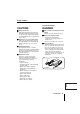
INSTRUCTION MANUAL VSP-9000 System Controller About this manual • Before installing and using this unit, please read this manual carefully. Be sure to keep it handy for later reference. • This manual gives basic connections and operating instructions.
Table of Contents Introduction Precautions (For UL) ...................................2 Safety Cautions............................................3 Major Characteristics ..................................8 Accessories..................................................8 Preparation Part Names ...................................................9 Menu Display..............................................11 System Information ...................................12 Sample System Connection .....................
Precautions (For UL) RISK OF ELECTRIC SHOCK DO NOT OPEN CAUTION: TO REDUCE THE RISK OF ELECTRIC SHOCK, DO NOT REMOVE COVER (OR BACK). NO USER-SERVICEABLE PARTS INSIDE. REFER SERVICING TO QUALIFIED SERVICE PERSONNEL. WARNING: To reduce the risk of fire or electric shock, do not expose this appliance to rain or moisture. CAUTION: Changes or modifications not expressly approved by the manufacturer may void the user's authority to operate this equipment.
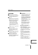
Safety Cautions Main Unit WARNING b Never use when unit emits smoke, unusual noises, or unusual smells. Using under these abnormal conditions can cause fires and electric shock. Immediately unplug the AC adapter power plug from the outlet, confirm that the smoke stops, and then request repairs from the installer or the purchasing source. Never attempt to repair the unit on your own, as this is dangerous.
Safety Cautions Provided AC Adapter CAUTION DANGER b Transport with care Unplug the AC adapter power plug from the outlet, confirm that connection cables are disconnected, and transport carefully to avoid dropping the unit or subjecting it to severe shock. b Only use with 100 to 240V power source voltage. This can cause fires and electric shock. b Cleaning the interior For cleaning the interior, consult the installer or the location of purchase.
Safety Cautions (Continued) Provided AC Adapter WARNING b Use only the provided AC adapter Use the provided AC adapter. Using a different AC adapter can cause fires or electric shock, due to differences in power cord current capacity. b Never touch the AC adapter with wet hands This can cause electric shock. English b Power plug Never use while abnormality is not corrected. The following situations can cause fires or electric shock.
Safety Cautions b Do not connect to other equipment The provided AC adapter is exclusively for this unit. Connecting to other equipment can cause fires or electric shock. b Power cord Damaging the power cord in the following manner can cause fires or electric shock. When the power cord is damaged, consult the installer or the location of purchase. • Never place a heavy object on the power cord, or expose to heating equipment, heated surfaces (front surface of heaters), or direct sunlight.
Safety Cautions (Continued) Always Observe These Rules for Proper Use b Trademark Brands and product names described in this document are trademarks or registered trademarks of their respective companies. b When not using for long periods Unplug the power plug from the outlet. However, this could damage the functions. Connect the power and operate the unit occasionally. b Fogging (Condensation) Drops of water form on the outside of a glass containing very cold water.
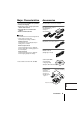
Major Characteristics Accessories • Use joystick for pan/tilt/zoom operations • Select your language • Wide-range control of high-speed dome cameras and receivers • Automatically test communication channels • RS485 communication line Check that all accessories are included.
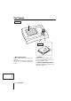
Part Names Front 1 2 Back 3 1 Menu Display (P11) 2 Joystick When the unit is turned on, the main menu is displayed. Press the buttons in the menu to display setup screens, etc. to access settings and operate the unit. This pans, tilts, and zooms the camera. It is also used to initialize the touch screen and to exit graphics settings. 3 Contrast adjustment volume This adjusts the brightness when the menu display is too dark to see.
Part Names Rear RS485 (RJ-11) Terminal A Signal B Signal SW COM A TELEMETRY B VIDEO 3 4 5 1 2 3 4 ON 12V 1 1 Power terminal Connect the DC terminal on the AC adapter provided. 2 Dipswitch (SW) Used for PC settings, communication settings, or terminate settings on this unit. SW 1 2 3 4 ON When using as a system controller, set to this position. (OFF) Use for ON/OFF settings for each terminate setup. When using the provided PC software.
Menu Display b System Information GENERAL INFORMATION UNDER SELECTION Present camera.......: Camera address.......: Monitor/Unit.........: A/B/V line...........: b System Setup esc 00001 00001 00001 V STILL MONITOR MENU 2 PLAY STOP LANGUAGE EXIT/OSD SYSTEM > TELEMETRY Connector.........(A): Protocol..........(A): Baudrate..........(A): Connector.........(B): Protocol..........(B): Baudrate..........(B): Video SANYO SSP ----Telemetry -------------- VIDEO Type.................: Protocol..........
System Information Press the button to display the current initial settings information for this unit. These settings change when communication line settings have been changed in System Setup. ALARM PLAY R PLAY PLAY SPEED PLAY SPEED PLAY STOP CLOCK ADJUST STILL ALARM REC SYSTEM SETUP REC STOP MAP ENTER TIMER ON/OFF ADDRESS ? 4 DVR GENERAL CAM 1 DVR INFORMATION esc 1 UNDER SELECTION Present camera.......: Camera address.......: Monitor/Unit.........: A/B/V line...........
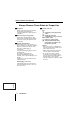
Sample System Connection A When connected to video communication terminal (VIDEO) A TELEMETRY B P15 Monitor VIDEO Modular cable Coaxial cable Conversion connector CARD MENU RESET Zoom camera EJECT RS485 A Terminal Zoom camera Zoom camera B When connected to video communication terminal (VIDEO) A TELEMETRY B Dome camera P18 Monitor VIDEO Modular cable A/B Coaxial cable Conversion connector B CARD MENU RESET Zoom camera EJECT RS485 A Terminal Zoom camera Zoom camera C When connect
Sample System Connection D When connected to video communication terminal (VIDEO) and camera communication terminal (TELEMETRY B) P24 (Competitor camera) A TELEMETRY B Monitor VIDEO Modular cable A/B Coaxial cable Conversion connector B CARD MENU RESET EJECT Zoom camera RS485 A Terminal Zoom camera Zoom camera Dome camera E When connected to video communication terminal (VIDEO) and camera communication terminals (TELEMETRY A/B) (Competitor camera) A/B Monitor VIDEO Modular cable Coaxial
Connection and Communication Setup 1 A When connected to video communication terminal (VIDEO) Zoom camera (sold separately) Dome camera (sold separately) Hard disk digital recorder with multiplexer function (sold separately) 2 1 IN MONITOR OUT MAIN A RS-485 B Monitor (sold separately) (A) (B) Provided communication conversion connector 3 2 3 1 AC adapter (provided) 3 3 SW 2 b Connecting communication conversion connectors G R R D B R Y L B K WH S L B L B R WH S L Preparation B L Eng
Connection and Communication Setup 1 b Making Connections b Communication Setup 1 Connect this unit to equipment 1 Press the for communication and operation. press the 2 Terminate Setup. 1 2 3 4 ON button, then button. The language selection screen (LANGUAGE) is displayed. Select a language if operating in a language other than English. (P42) Before connecting, make sure all equipment is turned off.
Connection and Communication Setup 1 (continued) Check Setup: • Type: To operate a hard disk digital recorder with a multiplexer function, this should display “DVR/MUX”. • Protocol: When “DVR/MUX” is selected for “Type”, “SANYO DVR/MU” is automatically displayed. • Baudrate: “19200” is automatically displayed. Match the settings of the connected equipment. 3 Press the esc button. esc button. Returns to Communication Setup (COMMUNICATIONS).
Connection and Communication Setup 2 B When connected to video communication terminal (VIDEO) Provided communication conversion connectors (Figure 2) Zoom camera Dome camera (sold separately) (sold separately) Zoom camera (sold separately) Zoom camera (sold separately) Hard disk digital recorder with multiplexer function (sold separately) 1 2 IN MONITOR OUT MAIN A RS-485 B Monitor (sold separately) (A) (B) Provided communication conversion connectors (Figure 1) 3 2 3 1 AC adapter (provided)
Connection and Communication Setup 2 (continued) b Making Connections b Communication Setup 1 Connect this unit to equipment 1 Press the for communication and operation. press the 2 Terminate Setup. 1 2 3 4 ON button, then button. The language selection screen (LANGUAGE) is displayed. Select a language if operating in a language other than English. (P42) Before connecting, make sure all equipment is turned off.
Connection and Communication Setup 2 Check Setup: • Type: To operate a hard disk digital recorder with a multiplexer function, this should display “DVR/MUX”. • Protocol: When “DVR/MUX” is selected for “Type”, “SANYO DVR/MU” is automatically displayed. • Baudrate: “19200” is automatically displayed. Match the settings of the connected equipment. 3 Press the esc button. esc button. Returns to Communication Setup (COMMUNICATIONS).
Connection and Communication Setup 3 C When connected to video communication terminal (VIDEO) and camera communication terminal (TELEMETRY A) Provided communication conversion connectors (Figure 2) Zoom camera Zoom camera Zoom camera Dome camera (sold separately) (sold separately) (sold separately) (sold separately) Hard disk digital recorder with multiplexer function (sold separately) 1 2 IN MONITOR OUT MAIN A RS-485 B Monitor (sold separately) (A) (B) Provided communication conversion connectors
Connection and Communication Setup 3 b Making Connections b Communication Setup 1 Connect this unit to equipment 1 Press the for communication and operation. press the 2 Terminate Setup. 1 2 3 4 ON button, then button. The language selection screen (LANGUAGE) is displayed. Select a language if operating in a language other than English. (P42) Before connecting, make sure all equipment is turned off.
Connection and Communication Setup 3 Check Setup: • Type: To operate a hard disk digital recorder with a multiplexer function, this should display “DVR/MUX”. • Protocol: When “DVR/MUX” is selected for “Type”, “SANYO DVR/MU” is automatically displayed. • Baudrate: “19200” is automatically displayed. Match the settings of the connected equipment (DVR, etc.). 3 Press the Returns to Communication Setup (COMMUNICATIONS).
Connection and Communication Setup 4 D When connected to video communication terminal (VIDEO) and camera communication terminal (TELEMETRY B) Provided communication conversion connectors (Figure 2) Zoom camera Zoom camera Zoom camera Dome camera (sold separately) (sold separately) (sold separately) (sold separately) (Competitor camera) Hard disk digital recorder with multiplexer function (sold separately) 1 2 IN MONITOR OUT MAIN A RS-485 B Monitor (sold separately) (A) (B) Provided communication
Connection and Communication Setup 4 (continued) b Making Connections b Communication Setup 1 Connect this unit to equipment 1 Press the for communication and operation. press the 2 Terminate Setup. 1 2 3 4 ON button, then button. The language selection screen (LANGUAGE) is displayed. Select a language if operating in a language other than English. (P42) Before connecting, make sure all equipment is turned off.
Connection and Communication Setup 4 Check Setup: • Type: To operate a hard disk digital recorder with a multiplexer function, this should display “DVR/MUX”. • Protocol: When “DVR/MUX” is selected for “Type”, “SANYO DVR/MU” is automatically displayed. • Baudrate: “19200” is automatically displayed. Match the settings of the connected equipment. esc button. Returns to Communication Setup (COMMUNICATIONS).
Connection and Communication Setup 5 E When connected to video communication terminal (VIDEO) and camera communication terminals (TELEMETRY A/B) Provided communication conversion connectors (Figure 2) Zoom camera Zoom camera Zoom camera Dome camera (sold separately) (sold separately) (sold separately) (sold separately) (Competitor camera) Hard disk digital recorder with multiplexer function (sold separately) 1 2 IN MONITOR OUT MAIN A RS-485 B Monitor (sold separately) (A) (B) Provided communication
Connection and Communication Setup 5 b Making Connections b Communication Setup 1 Connect this unit to equipment 1 Press the for communication and operation. press the 2 Terminate Setup. 1 2 3 4 ON button, then button. The language selection screen (LANGUAGE) is displayed. Select a language if operating in a language other than English. (P42) Before connecting, make sure all equipment is turned off.
Connection and Communication Setup 5 (continued) Check Setup: • Type: To operate a hard disk digital recorder with a multiplexer function, this should display “DVR/MUX”. • Protocol: When “DVR/MUX” is selected for “Type”, “SANYO DVR/MU” is automatically displayed. • Baudrate: “19200” is automatically displayed. Match the settings of the connected equipment. 3 Press the esc button. 4 Press the button, select “2–TELEMETRY”, then press the ent button. The “2–TELEMETRY” screen is displayed.
Communication Lines and Number of Connected Units This unit can operate multiple hard disk digital recorders with a multiplexer function connected to the rear video terminal (VIDEO), or multiple dome or zoom cameras connected to the camera terminals (TELEMETRY A/B). Address and terminate settings are required after connecting the equipment. See your operating manuals for proper settings of the connected equipment.
G R B R 1 WH S L SW Y L Communication Lines and Number of Connected Units (Continued) COM A TELEMETRY B R D B K B L SW O R 1 2 3 4 ON VIDEO G R G R B R WH S L 2 Y L B R WH S L Y L B R R D B L G R Y L B L O R B K B K SW O R R D WH S L 1 2 3 4 ON 12V COM A TELEMETRY B R D B K B L SW O R 1 2 3 4 ON VIDEO G R G R B R WH S L 3 Y L R D WH S L B R B R Y L B L G R Y L B L O R B K B K SW O R R D WH S L 1 2 3 4 ON 12V COM A TELEMETRY B R D B
Hard Disk Digital Recorder (DVR) Operation When connecting this unit with hard disk digital recorders, zoom cameras, etc. 1 Press the REC SYSTEM SETUP REC STOP MAP ENTER ALARM PLAY R PLAY PLAY SPEED PLAY SPEED STILL PLAY STOP CLOCK ADJUST TIMER ON/OFF SEQ ON SEQ/ PAN/ TOUR OFF ONE PUSH AF IRIS CENTER PAN ON TOUR ON ALARM FOCUS FAR IRIS FOCUS NEAR IRIS GO TO PRESET MUX button. DVR The address input screen appears, and Datum “00000” will flash.
Hard Disk Digital Recorder (DVR) Operation (Continued) 4 Press b Main Menu Screen Operation . changes to DVR . ALARM Datum: 00000 00000 Accept.values Max Min 00100 00001 1 4 7 2 5 8 0 3 esc 6 del DVR 9 PLAY t 5 Use the ten-key pad to enter the camera address (Example: 2). ALARM The Datum “00002” will flash. 3 esc 6 enter button. Press the 6 Datum: 00002 00000 1 4 2 REC 00000 Accept.values 00100 00001 Max Min Digit Camera nr.
Hard Disk Digital Recorder (DVR) Operation Recording stop button The recording stop screen is displayed on the menu display. TIMER ON/OFF Press esc to continue recording, or Plus display button While monitoring the main monitor multiple display screen, image from one camera is displayed larger. The display panes differ based on the number of camera input terminals. Press again to cancel. press enter to stop recording.
Hard Disk Digital Recorder (DVR) Operation (Continued) LOCK SEQUENCE MENU TO 10 KEY Security lock button Press to engage a security lock on hard disk digital recorder operation. COPY Camera sequence button This automatically switches the monitored live image. Press again to cancel. Menu button Press to display the hard disk digital recorder menu. COPY Ten-key screen switch button EXIT/OSD Press the esc button to return to the Menu screen.
Multiplexer (MUX) operation ALARM PLAY R PLAY PLAY SPEED PLAY SPEED PLAY STOP CLOCK ADJUST STILL REC SYSTEM SETUP REC STOP MAP ENTER ALARM TIMER ON/OFF ADDRESS ? 1 Press the The SEQ ON PAN ON SEQ/ PAN/ TOUR OFF TOUR ON ONE PUSH AF FOCUS FAR IRIS FOCUS NEAR IRIS GO TO PRESET 1 SPOT MON. 1 SPOT MON. 2 SPOT MON. 3 SPOT MON.
Multiplexer (MUX) operation (Continued) b Main Menu Screen Operation SPOT MON. 1 MAIN MONITOR 4 MENU Spot monitor buttons (*) Press to select the image to output to the spot monitor. NEXT SPOT MON. 2 SPOT MON. 3 b Sub Screen Operation SPOT MON. Main monitor button (*) Press to operate the main monitor. Multiple display button The main monitor displays a nine-pane or sixteen-pane screen. The display panes differ based on the number of camera input terminals.
Dome Camera/Zoom Camera Operation ALARM REC SYSTEM SETUP REC STOP MAP ENTER ALARM PLAY R PLAY PLAY SPEED PLAY SPEED STILL PLAY STOP CLOCK ADJUST TIMER ON/OFF SEQ ON SEQ/ PAN/ TOUR OFF ONE PUSH AF IRIS CENTER FOCUS FAR IRIS FOCUS NEAR IRIS 1 Press the The address input screen appears, and Datum “00000” will flash. DVR ADDRESS ? 3 PAN ON TOUR ON GO TO PRESET MUX 2 Use the ten-key pad to enter 4 TO SUB SCREEN the camera input channel (Example: 1), then press the enter button.
Dome Camera/Zoom Camera Operation (Continued) b Main Menu Screen Operation SEQ ON PAN ON TOUR ON SEQ/ PAN/ TOUR OFF Performs a sequential pan. Performs an automatic pan. Engages tour mode. b Sub Screen Operation AWB SET AWB RESET PRESET MEMORY Cancels sequential pan/automatic pan/tour mode. Press for an instant automatic white balance. Cancels white balance lock mode. Memorizes the current position, zoom, and focus under the specified preset position number.
Dome Camera/Zoom Camera Operation Turns OFF other functions. The ten-key pad screen is displayed on the menu display. Select the function number, and press the enter button. To return to the previous screen, press the esc button. Datum: 00000 00000 Accept.values Max Min 00016 00001 AUX: Digit Aux (Rst) nr. ZOOM PRESET ON ZOOM PRESET OFF BLC ON BLC OFF ELS ON ELS OFF CODE 1 4 7 . 2 5 8 0 3 esc 6 del 9 L-L PHASE Adjusts phase synchronization toward +.
System Setup Overview b Select Language Select the language displayed on the menu display.
Language Selection Passwords and menu display settings are available for operating this unit. As an example, changing the language (LANGUAGE) is explained here. Use the same method for other settings on the System screen. 1 Press the STILL MONITOR MENU 2 TIMER ALARM PLAY STOP CLEAR ENTER 2 SYSTEM SEARCH SEQUENCE ALARM REC STOP COPY AUTOFLIP PATROL PROG The System screen language selection REC screen 1 button or button, select a language, then press the ent button.
Communication Setup This sets up communication with equipment connected to the video communication terminal (VIDEO) or camera communication terminals (TELEMETRY A/B). Serial communication testing between connected equipment is also available.
Communication Setup 2 Press a number button b Unit Address Setup When purchased, the unit address is set to “1”. Change the address when using multiple controllers. Allocate addresses from 0 to 4. * The addresses can also be checked using the (example: 3), then press the enter button. The communication setup screen appears, and the address displays as 3. Entry range: 0, 1, 2, 3, 4 button. COMMUNICATIONS Datum: 1-VIDEO 1 4 7 .
Communication Setup (Continued) B 2–TELEMETRY (Dome camera or zoom camera communication setup) COMMUNICATIONS 2-TELEMETRY >A-Connector A-Protocol A-Baudrate B-Connector B-Protocol B-Baudrate Video SANYO SSP ----Telemetry -------------- esc ent Upon purchasing, the communication settings are set to connect our video equipment to cameras using coaxial cables. Communication uses the video communication terminal (VIDEO). For details, see “A-Connector”.
Communication Setup C 3–SERIAL TESTS (Communication output test for video communication terminal and camera communication terminal) ? the menu display. TESTS test!!! B:?? esc A:?? --------- ? Remove all lines connected to this unit, and use two modular cables and two communication converter connectors to connect as shown below.
Control Setup Sets up equipment and functions effective for this unit. b Select a Control Item (ACCEPTED VALUES) ACCEPTED Selection Items A 1–CAMERAS (Camera Communication Setup) VALUES >1-CAMERAS 2-MONITOR/LOCAL 3-FUNCTIONS DVR-MUX A C B ACCEPTED VALUES Dvr/Mux 001 1-CAMERAS > 1 11 21 31 51 61 71 81 91 A A A A A A A A A A A A A A A A -10 DVR-MUX DVR-MUX DVR-MUX +1 ent TEL Press the button or button to select a setup item, then press the ent button. Displays the selected screen.
Control Setup B 2–MONITOR/LOCAL DVR-MUX (Valid/Invalid setup for hard disk digital recorder with multiplexer function) Single row clear button Clears a row at a time.
Control Setup (Continued) C 3–FUNCTIONS ACCEPTED • MAPS environment Displays a user-created map when power is turned ON. VALUES 3-FUNCTIONS >1 -Mtx/Dvr/Mux setup.. 2 -Telemetry setup.... 3 -Autopan/Scan/Patrol 4 -Joystick........... 5 -Camera Up/Dw....... 6 -Address change..... 7 -Mon/Dvr/Mux change. 8 -Zoom/Focus/Iris.... 9 -Aux................ 10-Wiper/Washer....... 11-MAPS environment... 12-Spot Skip.......... esc ent Other functions can be started or stopped.
Password Setup (PASSWORD) Passwords can be set for operations upon unit power ON, setup menu access, etc. 1-AT SWITCHING ON Password required upon power ON PASSWORD Digit password Start >1-AT SWITCHING ON 2-ALARMS RESET 3-PARAM. MODIFICATION 4-GRAPH ENVIR. LEVEL 1 5-GRAPH ENVIR. LEVEL 2 6-GRAPH ENVIR. LEVEL 3 . 0 enter 2-ALARMS RESET Password required upon alarm reset ent Digit password Alarm reset . 0 enter 3-PARAM.
Password Setup (PASSWORD) (Continued) The password setup procedure is the same for each item. Here, entering the password upon unit power ON is explained. 2 Press number buttons to enter b AT SWITCHING ON (Power ON password) button or 1 Press the button to select “AT SWITCHING ON”, then press the ent button. the password, (example: 12345), then press the enter button. “Digit” changes to “Confirm”, and “*****” changes to “-----” (flashing). PASSWORD ---->1-AT SWITCHING ON 2-ALARMS RESET 3-PARAM.
Setup (CONFIGURATION) b Initialize b Buzzer and menu display setup CONFIGURATION CONFIGURATION 1-RESTORE >Confirm? BASIS 2-BUZZER/DISPLAY VALUES >1-Key pressed 2-Joystick 3-Serial error 4-Matrix alarm 5-Power saving (ENTER) : : : : : MAX YES YES YES NO ent ent b Joystick setup CONFIGURATION CONFIGURATION >1-RESTORE BASIS VALUES 2-BUZZER/DISPLAY 3-JOYSTICK 4-TOUCH SCREEN SETTING 5-TOUCH TEST 3-JOYSTICK >1-Released 2-All at right 3-All at left 4-All up 5-All down 6-Rotate zoom at 7-Rotate zoo
Setup (CONFIGURATION) (Continued) b Initialize (RESTORE BASIS VALUES) b Buzzer and menu display setup (BUZZER/DISPLAY) When this is set, the settings of each menu screen revert to the default settings. 1 Press the 1 Press the button or button to select “RESTORE BASIS VALUES”, then press the ent button. button or button to select “BUZZER/ DISPLAY”, then press the button. ent The “2–BUZZER/DISPLAY” screen is displayed. The “1–RESTORE BASIS VALUES” screen is displayed.
Setup (CONFIGURATION) • 4–Matrix alarm: Matrix alarm detection This setting sounds a buzzer when an alarm is detected. Selections: YES, NO • 5–Power saving: Power save function When no buttons are operated for approximately one minute, the screen brightness is automatically switched (dimmed). When another button operation is performed, the brightness returns to normal. Selections: YES, NO 3 Press the ent 2 Press the button or button to switch the joystick setting position.
Setup (CONFIGURATION) (Continued) b Touch screen adjustment (TOUCH SCREEN SETTING) button or 1 Press the button to select “TOUCH SCREEN SETTING”, then press the enter button. 3 Press the enter The coordinates at the upper left are placed in memory, and change to “= = = = =”. --------- The adjustment screen appears. ***** ***** button. 00524 03539 Enter 00425 03590 ESC Enter ESC 4 Press the button. The button at the upper left moves to the lower right.
Setup (CONFIGURATION) 6 Press the enter button. The coordinates at the lower right are placed in memory, and change to “= = = = =”. 7 Press the SAVE button. The coordinates at the upper left and lower right are in memory. --------- 03572 00737 b Touch Screen Initialization and Reset Initialize the set coordinates, and set the coordinates again. 1 Remove wiring and power cables for all equipment connected to this unit. 2 Turn dipswitch (SW1) ON.
Setup (CONFIGURATION) (Continued) 5 After initializing, operate the joystick as shown in the drawing to perform touch screen adjustment. 1 b Touch screen test (TOUCH TEST) 1 Press the button or button to select “TOUCH TEST”, then press the ent button. The testing screen appears. 2 The touch screen adjustment screen appears. Perform settings using the procedure on P55. --------- 00524 03539 Enter Keep your finger here to exit to the menu. ESC 2 Press the boxes on the test screen.
Software CONTENTS 2 Software Configuration ............................... 59 2 Connection and Software Installation........ 60 2 System Setup (Setup) .................................. 61 2 Language Setup (Language)....................... 68 2 Graphics Environment Setup (Maps) .........
Software Configuration Use the software on the provided CD-ROM to perform various settings for this unit on your PC. System Setup (Setup) P61 System setup for this unit are performed on the PC. The setting contents can be saved on the PC, making it efficient to manage differing settings, set one setting on multiple system controllers, or apply the same settings to all units. Language Setup (Language) P68 This allows creating new display languages for the unit, or changing individual words as desired.
Connection and Software Installation b Install the Software b Making Connections 1 Insert the provided CD-ROM in 3 Connect the PC connection the CD-ROM drive on the PC, open it, and click SETUP.EXE. The next screen is displayed. terminal (COM) on the rear panel of the unit to the PC serial port, using the computer connection cable (provided). Before connecting, make sure all equipment is turned off, and disconnect camera communication and video communication cables.
System Setup (Setup) Double-click 1 2 3 1 Menu [File] New: Create new system settings. Open: Open existing settings. Save: Save settings. Save as: Save settings by another name. Receive from keyboard: Download unit settings to this software. Send to keyboard: Upload software settings to the unit. COM Port: Select the PC port number (1 to 9). [Language] Select the menu display language for this software. [Exit] Exit the software. [Info] Display the software version.
System Setup (Setup) A General (General Settings) 2 3 1 4 2 1 4 1 From the “File” menu, select “New”. • To open saved settings, select “Open”. • To download the current unit settings and change them, select “Receive from keyboard”. 2 Click the [General] tab. 3 Make the various settings. (P63) 4 Make the various selections. • To make other settings, switch using the tabs and continue operation. • To save settings in the PC, on the “File” menu select “Save”.
System Setup (Setup) (Continued) 1 Language (Select Language): Each number corresponds to the number by each language displayed in the LANGUAGE screen under System Setup ( ). Check the display language and select the proper number. 2 Communications (Communication Setup): b When controlling a camera connected to our video equipment (Video) Upon purchasing, the communication settings are set for connecting to our video equipment (DVR/ MUX), and the settings do not need to be changed.
System Setup (Setup) B Cameras (Camera communication setup) 1 2 To change a camera address connected to another Dvr/Mux, change the Dvr/Mux address. 1 Click the [Cameras] tab. 2 Set camera lines using the various buttons. : Clear button Disconnects all cameras. 3 Select a camera for communication settings, double-click it, and click the button to display a menu. Select the desired status. : Single row clear button Clears a row at a time.
System Setup (Setup) (Continued) Changing the Camera Address Number • Click to enter input/output settings mode (upper left grid displays “Addr.”). To set a camera address, double-click it and enter the number. • To change the address of a camera connected to another hard disk digital recorder or multiplexer (Dvr/Mux), use the spin button to change the Dvr/Mux address. English 65 Software 4 Make the various selections. • To make other settings, switch using the tabs and continue operation.
System Setup (Setup) C Monitor/Local Mux (Valid/Invalid setup for hard disk digital recorder with multiplexer) 1 2 3 1 Click the [Monitor/Local Mux] tab. 2 Set the video equipment output using the various buttons. 4 Make the various selections. • To make other settings, switch using the tabs and continue operation. • To save settings in the PC, on the “File” menu select “Save”. • When selecting “Send to keyboard” on the “File” menu, the system setup content is uploaded to the unit.
System Setup (Setup) (Continued) D Enabling (stopping or starting settings) 1 Click the [Enabling] tab. 2 Check the functions to turn ON. Uncheck the functions to turn OFF, leaving them blank. • Setup Matrix/Dvr/Mux Enables display of the video equipment menu. • Setup Telemetry Enables display of the camera menu. • Autopan/Scan/Patrol Enables automatic operation of dome cameras. • Joystick Enables joystick operation. • Camera Up/Down Moves camera input channel up and down.
Language Setup (Language) Double-click 1 2 3 1 Menu 2 Toolbar [Text management] Receive from keyboard: Receives the current language from the unit. Load from file: Opens language settings file. Send to keyboard: Uploads software language settings to the unit. Save on file: Saves current language settings to a file. Special characters: Displays an input screen for special characters. COM Port: Select the PC port number (1 to 9). [Language] Select the menu display language for this software.
Language Setup (Language) (Continued) b Creating Two Different English Tabs 1 From the “Text management” menu, select “Receive from keyboard”. 2 Receives the current language Example: Creating Two Different English Language Setups 3 Select Tab 2 (English) in Window A, and Tab 7 in Window B. 4 Select “SCAN: digit” in from the unit. Window A, and click . The receive status is displayed on the screen, and the language is displayed when receiving is complete. “SCAN: digit” is copied to Window B.
Language Setup (Language) 7 Use the same procedure to change other words or change them into symbols, creating tabs with different English wording. Pressing will display the special character input screen. Enter the language name in the top row. 8 From the “Text management” menu, select “Send to keyboard”. English • This uploads these software language settings to the unit. • To save settings in the PC, on the “Text management” menu select “Save on file”.
Graphics Environment Setup (Maps) 1 2 3 Double-click English 1 Menu 2 Toolbar [Project] • New: Creates new graphics. • Open: Opens an existing file. • Save: Saves current settings. • Save as: Save settings by another name • Receive from keyboard: Downloads the current settings from the unit. • Send to keyboard: Upload software settings to the unit. • Print preview: Display a print preview of the settings list. • Print: Print a settings list. • COM port: Select the PC port number (1 to 9).
Graphics Environment Setup (Maps) b Display Telephone Number on Opening Screen 1 From the “Project” menu, select “New”. The Opening screen appears. 3 From the “Project” menu, select “Send to keyboard”. A dialog box is displayed for selecting the upload screen. Check the “Service” checkbox, and click the OK button. The pasted image is uploaded. Double-click 2 Click the “Service” tab, click “ ”, and select the image file to read. English Saving settings on PC From the “Project” menu, select “Save”.
Graphics Environment Setup (Maps) (Continued) b Map Screen Explanation 1 From the “Project” menu, select “New”. The Opening screen appears. Double-click 2 Click the [Maps] tab. The left window displays Map 1, and the right window displays the General icon.
Graphics Environment Setup (Maps) 1 Map Display 2 Map Selection Click the up or down arrows on the spin button to switch the map display screen. The following operations are available. Cancel key: Deletes a key. Copy key: Copies a key. Glue key: Pastes the copied key. Note: Maps 1 to 4 are basic displays for this unit, and cannot be changed (Locked). To allocate button functions, select Map 5 to 30. 3 Map selection button From the pull-down menu, select the map number to register.
Graphics Environment Setup (Maps) (Continued) (Allocation Setup Screen) (1) (5) (2) (6) (7) (3) (4) (1) Matrix/Mux-Dvr (5) Aux Allocates functions and selects video equipment and cameras for operation. Allocates other camera functions. (2) Movements Allocates dome camera automatic functions. See Protocol Chart (Autopan/Patrol). (P79, 80) (3) Focus/Iris Allocates camera focus and iris functions. (4) Jump page Allocates Map switching functions (Password levels can be set to perform this function).
Graphics Environment Setup (Maps) b Sample Equipment Allocation A To allocate “Play” to the hard disk digital recorder (DVR) at address 1 3 1 2 4 5 “1” in the text box (input field). 4 Check “Dvr Functions”, and select “Play” from the pull-down menu. 5 Press “Save and exit” to exit the screen. English 1 Check “Mixed System”. 2 Check “Local Dvr”.
Graphics Environment Setup (Maps) (Continued) B Select the camera connected to CH16 of the hard disk digital recorder (DVR) on address 2, and allocate “Autopan”. 3 4 1 2 5 6 1 Check “Mixed System”. 2 Check “Local Dvr”. 3 Check “Select Dvr”, and enter “2” in the text box (input field). 4 Check “Select camera”, and enter “16” in the text box. English 77 Software 5 Under Movements, under Autopan, click the radio button by “Start”, and enter “0” in the text box.
Graphics Environment Setup (Maps) C To switch the map display screen to Map 15 1 2 1 At the lower right of the screen, by “Jump page”, check “No.”, and enter “15” in the text box. 2 Press “Save and exit” to exit English the screen.
Graphics Environment Setup (Maps) (Continued) b Protocol Chart (Autopan) Protocol Start 1 Number Stop 2 Function ------------------ 1..32 START MULTISEQUENCE (*) ELBEX 0..2 0 START AUTOPAN 1 START AUTOPAN LEFT 2 START AUTOPAN RIGHT Number 1..32 Toggle 3 Function Number START SALVO (*) ELMO 0 START AUTOPAN 0 STOP AUTOPAN ENEO 0 START AUTOPAN 0 STOP AUTOPAN ERNITEC 0 START AUTOPAN FASTRAX 1..8 START AUTOPAN 1..
Graphics Environment Setup (Maps) b Protocol Chart (Patrol) Protocol ------------------ Start 4 Number Function 1..32 START TOUR (*) 0..3 START SEQUENCE 1..4 (0..3) Stop 5 Number Toggle 6 Function 0 STOP TOUR (*) 0 STOP PATROL 0 STOP PATROL Number Function 0 RESET TOUR(*) 0..1 TOGGLE PATROL STANDAR (0) TOGGLE PATROL S.A. (1) 0..1 TOGGLE PATROL STANDAR (0) TOGGLE PATROL S.A. (1) ELBEX ENEO 0 START PATROL ERNITEC 0 START PATROL FASTRAX 1..8 9..12 START TOUR 1..
Graphics Environment Setup (Maps) (Continued) b Changing the Opening screen to “SANYO” 3 Pastes the selected “SANYO” logo onto the opening screen. 1 From the “Project” menu, select “New”. The Opening screen appears. Double-click 4 From the “Project” menu, select “Send to keyboard”. A dialog box is displayed for selecting the upload screen. Check the “Opening” checkbox, and click the OK button. The pasted image is uploaded. 2 Click the “ ” icon, and select the image file to read.
Graphics Environment Setup (Maps) b Create a map using the graphics tool and display on opening screen. 2 From the “Images” menu, select “Change image”. A paint screen (FPaint) is displayed. Create a map or other graphic using the graphics tool. Opening Screen 1 From the “Project” menu, select “New”. English The Opening screen appears.
Graphics Environment Setup (Maps) (Continued) to save settings. 3 Click 4 From the “Project” menu, 1 select “Send to keyboard”. A dialog box is displayed for selecting the upload screen. Check the “Maps” checkbox, and click the OK button. The pasted image is uploaded. 2 3 4 1 General Tools : Cancel the entire drawing. : Cancel the previous operation (UNDO). : Delete the item selected with the cursor. : Display a grid or crosses for estimating the position. Check the pattern of your choice.
Graphics Environment Setup (Maps) b Basic Graphics 3 Drawing Tools : Selects the item (cursor) : Draws lines freehand 6 2 1 3 4 : Draws straight line : Draws rectangle (outline only) : Draws solid rectangle 5 : Draws rectangle with rounded corners (outline only) : Draws circle (outline only) : Draws solid circle : Specifies character insertion position (Characters are input into the text input area first) 4 Text input area To draw white lines, click “ black lines, click “ cursor. ”. To draw ”.
Specifications Communication Method RS485 Keyboard Backlight LCD, 320 x 240 touch screen Joystick Three-axis joystick (pan/tilt/zoom) Control terminal RJ-11 terminal: VIDEOx1, TELEMETERYx2 RS-232C terminal for PC D-SUB (9-pin): 1 terminal Dipswitch • Normal mode/PC mode: 1-bit dipswitch • Terminate: 3-bit dipswitch (Video/Telemetry A/B) Communication speed 2400, 4800, 9600, 19200 bps Maximum number of connected equipment Total: 256 units • Controller: 5 units • Multiplexer, hard disk digital
Appendix b Communications Chart 1–VIDEO (Video Line) Type Protocol Baudrate DVR/MUX SANYO DVR/MU 19200 Type Protocol Baudrate SANYO DVR/MU 2400, 4800, 9600, 19200 -------------- -------------- -------------- 4/2 VIDEOTEC MACRO MACRO NO P. 1200, 9600, 19200, 38400 1200, 9600, 19200, 38400 8/2 VIDEOTEC MACRO MACRO NO P. 1200, 9600, 19200, 38400 1200, 9600, 19200, 38400 8/4 VIDEOTEC MACRO MACRO NO P. 1200, 9600, 19200, 38400 1200, 9600, 19200, 38400 16/4 VIDEOTEC MACRO VIDEO TEC MACRO NO P.
Appendix (Continued) 2–TELEMETRY A (Camera Line) Connector Video A-CONNECTOR A-PROTOCOL A-Baudrate Video SANYO SSP ----- Telemetry A-CONNECTOR A-PROTOCOL A-Baudrate Telemetry SANYO SSP 19200 Protocol SANYO SSP SANYO HSSP Baudrate --------------- When any other protocol is selected, the connector is automatically displayed as “Telemetry”. SANYO SSP SANYO HSSP SENSORMAT. VCL VIDEOTEC -----------ERNITEC MACRO MARK M.
Appendix b Message Chart Message display ALARM: Esc to exit AUX: Select function AUX: Function not available AUX: Function not enabled AUX: Sent Set AUX: Sent Reset AUX: Sent Toggle AUTOFLIP: Function not available AUTOFLIP: Function not enabled AUTOFLIP: Sent enabled Autoflip AUTOFLIP: Sent Autoflip toggle AUTOFLIP: Sent Autoflip set AUTOFLIP: Sent Autoflip reset AUTOFLIP: Select function AUTOPAN: Select function AUTOPAN: Sent Autopan Start AUTOPAN: Sent Autopan Stop AUTOPAN: Sent Autopan Toggle AUTOPAN: F
Appendix (Continued) b Special Code Chart These functions can be loaded by entering their special codes. ERNITEC SATURN............................................ 89 MARK MERCER ................................................ 90 PELCO .............................................................. 92 SENSORMATIC ................................................. 94 b ERNITEC SATURN Code AUTOPAN 301 302 XXX PATROL 1000 1XXX 2000 2XXX 3XXX Function Saves the current position of the first limit switch.
Appendix Code Function IRIS MANUAL 11 Opens the iris. 12 Closes the iris. ON SCREEN DISPLAY 21 Screen display ON. 22 Screen display OFF. 23 Screen display on top half of monitor. Screen display on bottom half of monitor. 24 INFRARED RESPONSE CURVES 31 Initially set curve (visible light) 32 950nm curve 33 850nm curve COLOUR/B&W CAMERA 40 Automatically switch from color to black-and-white, and black-and-white to color.
Appendix (Continued) Code Function TOGGLE AUTO PARK (ON/OFF) 2XX Dome cameras can be set to automatically move to preset position No. 1 after a set stopping interval passes. XX= 01 – 99(*): Waiting time (minutes) before automatically stopping (*) when waiting time XX=00, the function is invalid.
Appendix Code Function 0 Pan 0 position SPEED CURVES 11 First speed curve (speed values: 1, 5, 10, 20, 30, 45, 63). 12 Second speed curve (speed values: 1, 10, 20, 30, 40, 50, 63). 13 Third speed curve (speed values: 10, 15, 20, 25, 30, 45, 63). 14 Fourth speed curve (default setting) (speed values: 29, 37, 45, 50, 55, 59, 63). 15 Fifth speed curve (speed values: 10, 15, 20, 30, 40, 50, 63). Sixth speed curve (Can be user customized, but has default settings: 16 10, 15, 20, 30, 55, 100, 255).
Appendix (Continued) Code Function ALARMS X Alarm identification (X is 1 to 8) MISC 99 Cleans screen. 999 Initializes remote camera operations (pan/tilt). 9999 Initializes remote camera operations (to default values). 70 Backlight compensation ON 71 Backlight compensation OFF 80 White balance ON 81 White balance OFF 90 Makes “unit phase delay mode” valid.
Appendix b SENSORMATIC PATTERN 51 52 53 55 56 61 62 63 71 72 73 MISC. 9999 Function All relays OFF Relay 1 ON Relay 2 ON Relay 3 ON Relay 4 ON Relay 1 and 2 ON Relay 1 and 3 ON Relay 1 and 4 ON Relay 2 and 3 ON Relay 2 and 4 ON Relay 3 and 4 ON Relay 1, 2 and 3 ON Relay 1, 2 and 4 ON Relay 1, 3 and 4 ON Relay 2, 3 and 4 ON Relay 1, 2, 3 and 4 ON Example: “13”: Makes only relays 1 and 3 valid (Relays 2 and 4 are invalid). “134”: Makes only relays 1, 3 and 4 valid (Relay 2 is invalid).
1AC6P1P2951-L8CSC/WA (0805KP)a VTECH SANYO Electric Co., Ltd.