
Installation Sheet

WARNING: Risk of Fire or Electric Shock
• Disconnect power before installation or any maintenance of the xture.
• To avoid damage, falling, electric shock or re, do not modify the xture
or replace accessories without conrming with the supplier rst.
• Only authorized, qualied personnel should install this xture and
should follow the owner’s manual.
• Do not dismantle the xture without the supplier’s authorization.
• Do not touch the power supply when the xture is operating.
• For use in environments where an accumulation of non-conductive
dust on the xture may be expected.
• Suitable for indoor/outdoor installations.
IMPORTANT: This product must be installed in accordance with the applicable installation
code by a person familiar with the construction and operation of the product and the
hazards involved.
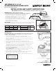
LED EDGE LIT 4", 6" & 8"
ROUND RECESSED DOWNLIGHTS
Models: S11826, S11827, S11828
Satco Products, Inc.
Brentwood, NY 11717
INSTALLATION
INSTALLATION AND SAFETY INSTRUCTIONS
IMPORTANT: Read before installing xture. Retain for future reference.
© Copyright 2020 Satco Products, Inc. 6/20
Model Dimensions Watts Volts CCT CRI Finish
S11826 4 inches 10W
120V
27K,30K,35K,40K,50K
90 WhiteS11827 6 inches 12W 27K,30K,35K,40K,50K
S11828 8 inches 24W 27K,30K,35K,40K,50K
Fixture Includes:
1 LED Lamp
1 Junction Box
TOOLS REQUIRED: Hole saw, measuring tape and connector cables (as needed).
NOTE: Use extensions if necessary. Available connector cables are 6' (1.8m).
Connector cables are linkable.
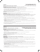
1. Turn power OFF from the electrical panel before starting installation.
2. Cut a hole in the ceiling for the downlight in a suitable position. Refer to Hole Cut
Dimension chart (below).
3. Run the electrical wire from the switch (power supply wire) through the mounting hole.
Use NMD90 Romex or BX cable. See Figure A.
4. Open the Junction Box swing cover and remove the appropriate knockouts.
5. Insert the power supply wire through the knockout and fasten with a cable connector
(not included).
6. Connect wires inside the Juction Box using the quick connect terminals. Connect green
ground with the green box wire. Connect the black and white power leads with the
matching black and white box wires. See Wiring Diagram.
7. Put all wires and connections back into the box and close the cover securely.
8. New Construction Applications: Juntion Box shall be firmly secured to the studs,
joists or similar fixed structural units.
Remodel Applications: Do not require the Junction Box to be firmly secured to xed
structural units. Remove the Junction Box tabs, then insert into ceiling.
9. Choose desired color temperature. See gure B.
10. Bend back the two torsion springs and slowly t the xture through the ceiling hole.
The torsion springs will pull the xture into place. See Figures C & D.
11. Once installation is complete, turn power ON to conrm the xture is working properly.
Hole Cut Dimensions:
4" xture = ø 4 3/16" (106mm)
6" xture = ø 6 3/16" (157mm)
8" xture = ø 8 3/16" (208mm)
WIRING DIAGRAM
Power supply
Cable to fixture
Green wires
Black wires
White wires
Quick connect
terminals