COMBITEK F 23 E Installation and Servicing Instructions IN WARRANTY TECHNICAL HELPLINE 01773 828400 THIS IS A CAT II2H3+ APPLIANCE 01773 828100 1
INSTALLATION AND SERVICING INSTRUCTIONS COMBITEK F 23 E Note: The boiler serial number is marked on the data label attached to the PCB housing behind the front lower section. Refer to the ‘Introduction’ section for a description of the basic functions of the boiler. The ‘User’ section describes how to safely operate the boiler. Users’ Instructions Introduction ..................................................... Page 2 Controls and lighting .................................................
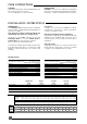
USER INSTRUCTIONS 2 The control panel is located on the front bottom section. The controls on this panel allow the boiler to be started, shut down and controlled during use.
USER INSTRUCTIONS CLEANING The boiler casing can be cleaned with a damp cloth followed by a dry cloth to polish. Do not use abrasive or solvent cleaners. BOILER CASING CAUTION: Do not remove or adjust the casing in any way, as incorrect fitting may result in faulty operation. If in doubt, contact your Installer/Service Provider. INSTALLATION INSTRUCTIONS Accessories A range of accessories are available including, vertical flue components. For further information, contact you nearest stockist.
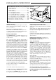
INSTALLATION INSTRUCTIONS Pump: Available pressure (kPa) between heating flow and return The performance of the pump varies according to the pump bypass setting, see diagram 3.
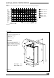
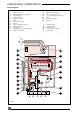
INSTALLATION INSTRUCTIONS BOILER SCHEMATIC 3 4 6 7 8 9 10 11 12 13 14 16 17 - Ignition module Heating temperature adjuster Pressure gauge non-return valve Expansion vessel Pump Automatic air vent Burner Burner pressure test point Heat exchanger Gas valve Heating and hot water thermistor Ignition electrode 19 20 21 22 23 24 - Overheat thermostat Flame sense electrode Loss of water pressure switch Fan Air pressure switch Gas cock A B C D E - Heating return Cold water inlet Heating flow Domestic hot w
INSTALLATION INSTRUCTIONS Minimum dimensions (in mm) for the positioning of flue terminals - Under a window .............................................. Under an air vent ............................................ Under a gutter ................................................. Under a balcony ............................................. From an adjacent window ............................ From an adjacent air vent ............................. From vertical drain pipes or soil pipes ..........
INSTALLATION INSTRUCTIONS Filter Fibre washer B Diagram 7b Pla 277 Isolating cock Flow restrictor Boiler connections A Heating return B Cold water mains inlet C Heating flow D Hot water outlet E Gas connection F Safety valve discharge connection Pla 275 F A B D C E Diagram 7a Installing the boiler Prior to installing the boiler, the system must be thoroughly flushed to eliminate any foreign bodies and contaminents such as filings, solder, particles, oil, grease etc.
INSTALLATION INSTRUCTIONS HORIZONTAL FLUE INSTALLATION • Fit gasket (H) onto underside of elbow (C) • Carefully insert ‘o’ rings (J) into upper and lower parts of inner elbow • Fit elbow onto boiler using screws provided (I) • Offer flue pipes to elbow, note that pipe (B) should be inside pipe (A) before connection. Push pipe (B) into inner elbow socket and connect pipe (A) with collar (D). Locking clips (E) are used to lock collar into position.
INSTALLATION INSTRUCTIONS VERTICAL FLUE INSTALLATION A .................................................................... Gasket B ..................................................... Vertical adaptor C .................................................................... ‘O’ ring D ....................................................................... Collar E ...................................................................... Clamp F ..................................................................
INSTALLATION INSTRUCTIONS DO NOT INTERRUPT THE MAINS SUPPLY TO THE BOILER WITH A TIME SWITCH OR PROGRAMMER. ELECTRICAL CONNECTION Warning: This boiler must be earthed. All system components must be of an approved type. Connection of the whole electrical system and any heating system controls to the electrical supply must be through a common isolator. Isolation should preferably be by a double pole switched fuse spur box having a minimum contact separation of 3 mm on each pole.
INSTALLATION INSTRUCTIONS COMMISSIONING The commissioning and first firing of the boiler must only be done by a competent person. Diagram 14 Filling the system 2 Open isolating coks to boiler (see diagram 7a) 3 Sec 058 Open the tap on the system filling loop and fill the system until the pressure indicated on the display is between 1 and 2 bar. Reg 008 Undo, but do not remove, cap on automatic air vent on top of pump. Do not retighten cap. 5 Open various hot water taps to bleed system.
Gas pressures The main burner pressure should be checked during commissioning to make sure the correct output is obtained. Proceed as follows: • Shut down boiler. • Undo screw on burner pressure test point below sealed combustion chamber and connect a suitable manometer, see diagram 15. • Start boiler as described in 'User Instructions'. • Set boiler thermostat to maximum and check that any external controls are calling for heat.
INSTALLATION INSTRUCTIONS SETTINGS Gas valve setting All boilers are tested and factory set during manufacture. Should it be necessary to reset a gas valve, for example after replacement, proceed as follows: • Shut down boiler. • Connect a suitable pressure gauge as described in 'Commissioning'. Diagram 17 Reg 013 Diagram 18 Reg 057 Mec 121 Maximum setting • Remove one electrical connector from the modulating gas valve coil. • Turn the domestic hot water temperature adjuster to maximum setting.
ROUTINE CLEANING ANS INSPECTION To ensure the continued efficient and safe operation of the boiler it is recommended that it is checked and serviced at regular intervals. The frequency of servicing will depend upon the particular installation conditions and usage, but in general once a year should be enough. It is the law that any servicing is carried out by a competent person. Service Check and Preparation. • Operate boiler and check for any faults that need to be put right.
SERVICING INSTRUCTIONS To replace fan • Disconnect power supply and earth leads to fan. • Unscrew and remove two fan retaining screws located at front edge of fan mounting plate. • Remove fan with mounting plate attached by pulling forwards and out of boiler. • Unscrew and remove three screws securing fan to fan mounting plate. • Fit replacement fan to mounting plate and secure with screws.
To replace reversing valve assembly • Remove pressure gauge capillary as described previously. • Remove pump as described previously. • Remove microswitch assembly as described previously. • Remove retaining clip from LHS pipe connection on front section of valve and disengage pipe. • Unscrew and disconnect heating flow (centre) connection at fixing jig. • Remove retaining clip from heating flow pipe connection on right of front section. • Remove flow pipe from boiler.
SERVICING INSTRUCTIONS To replace reversing valve front section • Remove pressure gauge capillary as described previously. • Remove pipe connections from either side of reversing valve front section, refer to previous section. • Move short selector lever on front of valve to left hand position. • From below boiler, undo and remove single screw holding reversing valve front plate to bottom plate of boiler. • Undo and remove six screws holding front section to rear section of reversing valve, see diagram 25.
To replace gas valve • Ensure gas supply is off. • Disconnect two black electrical leads from gas valve modulating coil. • Disconnect two white and one red lead from gas valve main solenoid. • Pull off clear plastic tube from gas valve to sealed chamber tapping point. • Unscrew main gas supply pipe nut on top of gas valve, releasing spark ignition unit bracket, see diagram 27. • From below boiler, unscrew gas valve connection between gas valve and isolating cock.
SERVICING INSTRUCTIONS 1 Boiler in place Note: The expansion vessel can be replaced with the boiler in place provided that there is a minimum clearance of 400mm on one side of the boiler and that no vertical pipework passes between boiler and wall on that side. • Drain down the heating circuit of the boiler only as described in 'To replace pump'. Note: It is not necessary to drain entire heating system to carry out this work. • Remove pump from boiler as described previously.
SERVICING INSTRUCTIONS To replace flame sense electrode • Remove combustion chamber from boiler as described in 'Routine Cleaning and Inspection'. • Pull off lead from flame sense electrode. • Unscrew and remove screw holding earth lead to flame sense electrode. • Unscrew and remove screw holding flame sense electrode onto burner. • Fit replacement flame sense electrode in reverse order to removal. • Refit lead. To replace burner • Pull off ignition and flame sense leads from electrodes.
SERVICING INSTRUCTIONS EV2 13.2 13.3 12.1 8.1 12.2 13.1 13.4 14.7 14.2 14.1 14.3 14.4 14.5 Pr 14.6 FL 14.8 14.9 K4 EV1 Al Ex FA SCHEMATIC WIRING DIAGRAM L N 2.1 2.2 CTN 6.3 6.6 6.4 6.2 6.8 K5 6.12 P SW3 6.15 6.9 Ra 6.14 6.11 TA EV3 6.13 9.1 9.2 8.4 8.3 TRA 8.
SERVICING INSTRUCTIONS FAULT FINDING Prior to fault finding, check : Inlet gas pressure = 20 mbar Electrical supply = 240 V - 50 Hz Central heating system is pressurised at 1 - 1,5 bar. Overheat thermostat on RHS of heat exchanger has not tripped reset if necessary. Carry out electrical system checks i.e. earth continuity, resistance to earth, short circuit and polarity with a suitable meter. Note : these must be repeated after any servicing or fault finding.
SERVICING INSTRUCTIONS Open hot tap fully. Does burner fire ? PUMP NOT RUNNING NO HOT WATER Is there 240 v at pump ? NO With selector switch/thermostat NO in position and turner to maximum.