
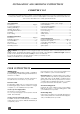
Technical data


7
N
C
D
M
A
B
E
F
G
I
H
L
Ven 060b
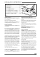
Diagram 6
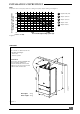
Minimum dimensions (in mm) for the positioning of flue terminals
A-Under a window .............................................. 300
B-Under an air vent ............................................ 300
C-Under a gutter ................................................. 75
D-Under a balcony ............................................. 300
E-From an adjacent window ............................ 300
F-From an adjacent air vent ............................. 300
G-From vertical drain pipes or soil pipes .......... 75
H-From an external corner of the building ...... 300
I-From an internal corner of the building ....... 300
L-From the ground or from another floor ........ 300
M- Between two terminals vertically .................. 1500
N-Between two terminals horizontally .............. 300
TERMINAL POSITIONS
The minimum acceptable spacings from the termi-
nal to obstructions and ventilation openings are
shown in diagram 6 :
Cupboard or compartment ventilation
The boiler can be fitted in a cupboard or
compartment without the need for additional per-
manent high and low level ventilation
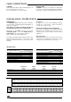
HEATING SYSTEM DESIGN
The combitek F 23 E is compatible with any type of
sealed system installation, i.e. radiators, fan
convectors etc.
Pipe sectional areas shall be determined in
accordance with normal practices, using the pump
curve, refer to ‘Technical Data’. The distribution system
shall be calculated in accordance with the output
requirements of the actual system, not the maxi-
mum output of the boiler. However, provision shall be
made to ensure sufficient flow so that the temperature
difference between the flow and return pipes is less
than or equal to 20
o
C. The minimum flow is 500 l/h.
The piping system shall be routed so as to avoid any
air pockets and facilitate permanent venting of the
installation. Bleed fittings shall be provided at every
high point of the system and on all radiators.
The total volume of water permitted for the heating
system depends, amongst other things, on the static
head in the cold condition. The expansion vessel on
the boiler is pressurised at 0,5 bar (corresponding to
a static head of 5m wg.) and allows a maximum
system volume of 140 litres for an average
temperature of 75
o
C and a maximum service pres-
sure of 3 bar. This pressure setting can be modified at
commissioning stage if the static head differs.
Provision shall be made for a drain valve at the
lowest point of the system.
Thermostatic radiator valves are permitted.
A suitable WRC approved filling loop must be fitted
to enable correct filling of the system.
In all cases, it is ESSENTIAL that the system be
thoroughly flushed prior to installing the new boiler.
DOMESTIC HOT WATER SYSTEM DESIGN
Copper tubing must be used for the domestic hot
water system. Unnecessary pressure losses should be
avoided.
The domestic hot water supply pressure must be
between 0.5 and 10 bar. If the pressure exceeds 3
bar, a pressure reducing valve must be fitted.
Hard water areas
In areas where the water hardness exceeds 200 mg/
litre, it is recommended that a suitable scale reducing
device is fitted.
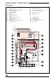
Heating system connections - Pipe Ø 22 mm.
Hot water system connections - Pipe Ø 15 mm.
Gas connection - Pipe Ø 22mm.
Safety valve discharge
WARNING: It must not discharge above an entrance
or window or any type of public access area.
Connect the safety valve discharge pipe to the
valve, the discharge must be extended using not
less than 15 mm o.d. pipe, to discharge in a visible
position outside the building, facing downward,
preferably over a drain. The pipe must have a
continuous fall and be routed to a position so that
any discharge of water, possibly boiling or steam,
cannot create any danger to persons, damage to
property or external electrical components and
wiring. Tighten all pipe connection joints.
Gas connection
The supply from the governed meter must be of
adequate size to provide a constant inlet working
pressure of 20 mbar (8 in wg).
To avoid low pressure problems, it is recommended
that the supply is taken to the boiler using 22 mm
pipe as far as possible.
On completion, the gas installation must be tested
using the pressure drop method and purged in
accordance with the current issue of BS6891.
Gas Safety (Installation and Use) Regulations.
In your interests and that of gas safety, it is the law
that ALL gas appliances are installed and serviced
by a competent person in accordance with the
above regulations.
INSTALLATION INSTRUCTIONS