
Technical data


9
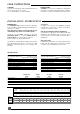
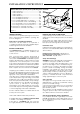
HORIZONTAL FLUE INSTALLATION
• Fit gasket (H) onto underside of elbow (C)
• Carefully insert ‘o’ rings (J) into upper and lower
parts of inner elbow
• Fit elbow onto boiler using screws provided (I)
• Offer flue pipes to elbow, note that pipe (B) should
be inside pipe (A) before connection. Push pipe
(B) into inner elbow socket and connect pipe (A)
with collar (D). Locking clips (E) are used to lock
collar into position.
• Parts (F) and (G) are used to seal brickwork gaps
if required. If using part (G) to seal inner wall, this
should be placed over flue before installation.
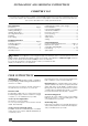
Calculation of flue cutting lengths
· Measure wall thickness e (mm)
· For side flues, measure distance from inside face of
the side wall to the centre line of the boiler and
subtract 205 mm to get dimension a (mm) see
diagram 10.
· Refere to table 1 for the cutting lenghs of both
the inner and outer flue pipes for each of the
various flue options available.
· Important: All flue cutting lengths must be
measured from the terminal end of the flue pipes,
see diagram 11.
· When the dimension x measured on site is greater
than that given in table 1 a flue extension kit will be
required, refere to table 2 for details.
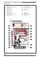
INSTALLATION INSTRUCTIONS
Diagram 9
Pho 422
The flue kit 86285 is 1000 mm long and com-
prises:
- Outer pipe .................................................... A
- Inner pipe ....................................................... B
- Flue elbow..................................................... C
- Fixing collar ................................................... D
- Locking clips .................................................. E
- External rubber sealing collar ..................... F
- Internal flange .............................................. G
- Gasket ........................................................... H
- Screws.............................................................. I
- 'O' rings ........................................................... J
A
B
I
GE
C
F
J
H
D
Table 1
Flue cutting lengths
Cutting length (mm)
Flue option outer pipe inner pipe Comments
Top outlet e + 144 e + 224 maximum
rear flue wall thickness "e"
without
extension
511 mm
Table 2
Number of extension kits required
Flue option Dimension 'X' No. of
extension kits
Side flue 745 to 1745 mm 1
(left or right) 1527 to 2745 mm 2
Hab 210
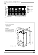
Diagram 10
ee
a
a
X
X
Ven 089
Diagram 11
Cutting length
Outer pipe
Inner pipe
Cutting length
Maximum horizontal flue run 3m
For each 90
o
flue bend fitted, reduce overall flue
length by 1 m.
For each 45
o
flue bend fitted, reduce overall flue
length by 0.5 m.
Horizontal flue kit 86285
Flue extension kit 85091
90
o
bend kit 85092
45
o
bend kit 85093