Heating and hot water for the professionals ECOSY ECOSY 24 E, ECOSY 5B 24 E is CAT II2H3+ appliances IN WARRANTY TECHNICAL HELPLINE 01773 828400 ECOSY 28 E, ECOSY 5B 28 E is CAT I2H appliances 01773 828100 1
INSTALLATION AND OPERATING INSTRUCTIONS ECOSY 24 E, ECOSY SB 24 E ECOSY 28 E, ECOSY SB 28 E Note! The boiler serial number is marked on the label attached to the top of the inner bulkhead. Refer to the 'Introduction' section page 3 for a description of the basic functions of the boiler. The 'Users' section describes how to safely operate the boiler. USERS SECTION Introduction .................................................. Page 3 Commissioning .......................................................
INTRODUCTION The ECOSY 24 E and ECOSY 28 E boilers are wall mounted combination boilers providing central heating and instantaneous hot water. The ECOSY SB 24 E and ECOSY SB 28 E boilers are wall mounted system boiler providing central heating only. The ECOSY 24 E and ECOSY SB 24 E boilers are of the II2H3+ category for use with Natural Gas (G20) and Liquide gas (G30 and G31)as distributed in the United Kingdom.
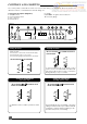
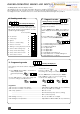
CONTROLS AND LIGHTING The control panel, located at the lower front of the boiler casing, see diagram 2, allows the boiler to be started, shut down, controlled and monitored during use.
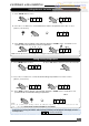
CONTROLS AND LIGHTING Setting domestic hot water temperature 1 - Press «Mode» button once ➭ 1. 65 set ➭ 2. 65 ➜ mode 2 - Press «+» or «-» button to set the desired hot water temperature from 40°C to 65°C (factory set at 65°C) 2. 6 0 ➭ - + ➭ 2. 60 set ➭ 1. 65 twice Hab 198a enter ➜ 3 - Press «enter» until the display starts flashing, and press «mode» twice : the boiler is now operational at the desired hot water temperature.
BOILER OPERATING MODES AND DISPLAY READINGS The Ecosy display has three display modes : A - Reading mode only - this gives information about the operation in progress. B - Programming mode - this allows the user to change selected settings of the boiler. C - Diagnostic mode - this allows the user to check selected temperatures during boiler operation.
DRAINING Protection against freezing If the boiler is to be out of use for any long periods during severe weather conditions, it is recommended that the whole system, including the boiler, be drained to avoid the risk of freezing. If in doubt, consult your servicing company. The ECOSY boilers have a built in frost protection device that protects the boiler from freezing.
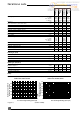
Heating output Efficiency Part load efficiency 30% (50°C/30°C) Maximum heating temperature Expansion vessel effective capacity Expansion vessel charge pressure Maximum system capacity at 75°C Safety valve, maximum service pressure Products outlet Fresh air inlet Hot water output Maximum hot water temperature automatically adjustable from (kW) to (kW) from (Btu/H) to (Btu/H) (%) (%) (°C) (l) (bar) (l) (bar) (mm) (mm) ECOSY SB 28 E ECOSY 28 E ECOSY SB 24 E ECOSY 24 E TECHNICAL DATA 6,8 6,8 24,5 24,5
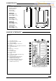
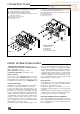
DIMENSIONS Diagram 4 201,5 227 890 (Ecosy 24 E/SB 24 E) 890 985 (Ecosy 28 E/SB 28 E) The boiler is delivered in three separate packages : - the boiler itself - the fixing jig - the flue system ECOSY 24 E Net weight : 68 kg Gross weight : 72 kg ECOSY SB 24 E Net weight : 58 kg Gross weight : 62 kg Hab 204a ECOSY SB 28 E Net weight : 63 kg Gross weight : 77 kg 140 ECOSY 28 E Net weight : 73 kg Gross weight : 87 kg 520 373 BOILER SCHEMATIC Diagram 5 2 ➞ 1 17 3 4 5 16 15 6 8 18 7 19 9 14
CONNECTION PLATE ECOSY SB 24 E, ECOSY SB 28 E From left to right, the connection plate is equipped with: A - Heating return with isolating valve (m). C - Heating flow with isolating valve (q), drain screw (r) and safety valve (s). E - Electrical connector. F - Gas service cock. ECOSY 24 E, ECOSY 28 E From left to right, the connection plate is equipped with: A - Heating return with isolating valve (m). B - Cold water inlet with isolating valve (p).
HEATING SYSTEM DESIGN Ecosy SB 24 E/SB 28 E : 1 bar (corresponding to a static head of 10 m w.g.) and allows a maximum system volume of 215 l, for an average temperature of 75°C and a maximum service pressure of 3 bar. This pressure setting can be modified at commissioning stage if the static head differs. An additional expansion vessel can be fitted to the system if required, see diagram 8. The ECOSY boilers are compatible with any type of installation.
DOMESTIC HOT WATER SYSTEM DESIGN ECOSY 24 E/ 28 E only ● Copper tubing must be used for the domestic hot water system. Unnecessary pressure losses should be avoided. ● A flow restrictor is factory fitted in the cold water inlet before the thermostatic valve. This limits the flow through the boiler to a maximum of 12 l/min. Hard water areas The temperatures within the heat exanger are limited by the boiler control system to minimise scale formation within the hot water pipework.
BOILER INSTALLATION Statutory requirements The installation of this boiler must be carried out by a competent person in accordance with the relevant requirements of the current issue of: Connect the various couplings between boiler and connection plate. ● Fit water trap supplied (diagram 11) to the condense outlet located underneath and to the left rear of the boiler.
FLUE INSTALLATION 20 B - Flue to side of boiler ● Mark the horizontal centre line for the hole on the rear wall. Extend the horizontal centre line to the side wall and mark the vertical centre line of flue hole as shown in diagram 13. 33 103 The boiler is only suitable for top outlet flue connection. A - Flue to rear of boiler ● Mark correct position of hole from template.
FLUE INSTALLATION Extended flue The horizontal flue is extended by using one or more of the 1000 mm extension pipes part number 85452. These are connected together by push fit type joints. Calculation of flue cutting lengths for extended flue ● Using the correct number of extension kits as table 2, measure dimensions a and e, see diagram 14. Cut both the inner and outer pipe to the dimension given in table 3.
ELECTRICAL CONNECTION Warning. This boiler must be earthed All system components must be of an approved type. Connection of the whole electrical system and any heating system controls to the electrical supply must be through a common isolator. Isolation should preferably be by a double pole switched fused spur box having a minimum contact separation of 3 mm on each pole. The fused spur box should be readily accessible and preferably adjacent to the boiler. It should be identified as to its use.
COMMISSIONING The commissioning and first firing of the boiler must only be done by a competent person. Gas installation It is recommended that any air is purged from the supply at the gas inlet test point on the lower right hand side of the gas valve, see diagram 19. Filling the system ● Open shut off valves (see diag. 6 or 7 as appropriate) (slot of screw corresponds to flow direction), and caps on automatic air vents on top RHS of boiler. ● Bleed each radiator until a continuous jet of water is obtained.
OPERATING SAFETY DEVICES Gas leak or fault If a gas leak or fault exists or is suspected, turn the boiler off and consult the local gas undertaking or your installation/servicing company. attempt to relight. If the fault persists after 20 attempted relights, the boiler shuts down and requires a manual reset. Check pump speed and flow rate of the circulating system. In case of power supply failure The boiler no longer operates.
SETTINGS Alternatively, connect a CO2 analyser to the combustion test point on the flue elbow. ● Start the boiler. ● Press the «Mode» and «+» buttons simultaneously, the letter H is displayed and the boiler is now running at high gas flow rate. ● Allow the boiler to run for a few minutes to stabilise and check the CO2 value, refer to table 4. ● At the 28E and SB28E the CO2 at high gas flow rate is automatically controlled. ● At the 24E and SB24E the CO2 at high gas flow rate can be adjusted.
CHANGING GAS TYPE Conversion to a different type of gas only for ECOSY 24 E and ECOSY SB 24 E : Note : Conversion to a different type of gas is only possible with category II2H3+ appliances ! Conversion to a different type of gas must only be carried out by a specialist registered with the GVU or specialist authorised by Unical. Note : The appliances are normally supplied with the desired type of gas. Gas conversion units for other types of gas must be ordered separately.