
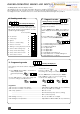
Operating instructions


10
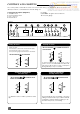
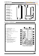
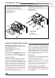
CONNECTION PLATE
ECOSY 24 E, ECOSY 28 E
From left to right, the connection plate is equipped with:
A - Heating return with isolating valve (m).
B - Cold water inlet with isolating valve (p).
C - Heating flow with isolating valve (q), drain screw (r)
and safety valve (s).
D - Domestic hot water outlet.
E - Electrical connector.
F - Gas service cock.
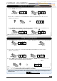
ECOSY SB 24 E, ECOSY SB 28 E
From left to right, the connection plate is equipped with:
A - Heating return with isolating valve (m).
C - Heating flow with isolating valve (q), drain screw (r)
and safety valve (s).
E - Electrical connector.
F - Gas service cock.
Pla 144a
PIPING SYSTEM INSTALLATION
Heating system connections - Pipe diam 22 mm
● Hot water system connections (ECOSY 24 E/ 28 E
only) - Pipe diam 15 mm
● Gas connection - Pipe diam 22 mm
● Safety valve discharge - Pipe diam 22 mm
Water connection
Connect the copper tails and isolating cocks sup-
plied, to the boiler, see diagram 6 or 7. Connect the
system pipework to the boiler observing the correct
flow and return format as shown in diagram 6 or 7.
Safety valve discharge
WARNING. It must not discharge above an entrance
or window or any type of public access area.
Connect the safety valve discharge pipe to the
boiler, the discharge must be extended using not
less than 15 m o.d. pipe, to discharge in a visible
position outside the building, facing downward pref-
erably over a drain. The pipe must have a continu-
ous fall and be routed to a position so that any dis-
charge of water, possibly boiling or steam, cannot
create any danger to persons, damage to prop-
erty or external electrical components and wiring.
Tighten all pipe connection joints.
Gas connection
● The supply from the governed gas meter must be
of adequate size to provide a constant inlet work-
ing pressure of 20 mbar (8 in w.g.).
To avoid low gas pressure problems, it is recom-
mended that the gas supply is connected using 22
mm pipe.
● On completion, the gas installation must be tested
using the pressure drop method and purged in ac-
cordance with the current issue of BS6891.
Gas Safety (Installation and use) Regulations
In your interests and that of gas safety, it is the law
that ALL gas appliances are installed and serviced
by a competent person in accordance with the
above regulations.
1
2
3
4
5
6
55
55
57,5
57,5
r
p
q
34
25
23
113
s
33
A
B
C
D
F
E
m
Diagram 6
Filters and washers :
1 - Fibre washer
2 - Metal filter
3 - Plastic filter
4, 5 & 6 - Black graphite
1
2
5
7
r
p
q
25
23
113
s
A
C
F
E
m
115
110
Diagram 7
Pla 202