
Operating instructions


8
Heating output automatically adjustable from (kW) 6,8 6,8 8,9 8,9
to (kW) 24,5 24,5 28,8 28,8
from (Btu/H) 23217 23217 30386 30386
to (Btu/H) 83649 83649 98330 98330
Efficiency (%) 98,9 98,9 97,5 97,5
Part load efficiency 30% (50°C/30°C) (%) 109,3 109,3 106,8 106,8
Maximum heating temperature (°C) 90 90 90 90
Expansion vessel effective capacity (l) 7 12 7 12
Expansion vessel charge pressure (bar) 0,5 1 0,5 1
Maximum system capacity at 75°C (l) 150 215 150 215
Safety valve, maximum service pressure (bar) 3 3 3 3
Products outlet (mm) Ø 60 Ø 60 Ø 60 Ø 60
Fresh air inlet (mm) Ø 100 Ø 100 Ø 100 Ø 100
Hot water output automatically variable from (kW) 6,8 — 8,9 —
to (kW) 24 — 28,8 —
from (Btu/H) 23,21 — 30386 —
to (Btu/H) 81,89 — 98330 —
Maximum hot water temperature (°C) 65 — 65 —
Specific flow rate (for 30°C temperature rise) l/min 11,4 — 13,3 —
Maximum supply pressure (bar) 8 — 8 —
Electrical supply (V) 230 230 230 230
Maximum absorbed power (W) 115 115 132 132
ECOSY 24 E
ECOSY SB
24 E
TECHNICAL DATA
Ø Burner injector (mm) 4,9 4,9 5,6 5,6
Supply pressure (mbar) 20 20 20 20
Gas rate (maximum) (m
3
/h) 2,6 2,6 3,0 3,0
Gas rate (minimum) (m
3
/h) 0,7 0,7 0,9 0,9
Natural gas (G20)
(10 kPa = 1 mWG)
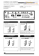
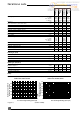
Available pressure between
heating flow and return
Available pressure between
heating flow and return
flow rate through heating system (l/h)
0
10
20
30
50
60
70
40
500 1000 1500 2000
2
flow rate through heating system (l/h)
Diagram 3
1
2
3
0
10
20
30
50
40
500 1000 1500
Pump :
Note : Curves 1,2 and 3 correspond to each of the three pump speed settings.
ECOSY 24 E, ECOSY SB 24 E ECOSY 28 E, ECOSY SB 28 E
ECOSY SB
28 E
ECOSY 28 E
Pom 043 c
Liquide gas (G30/G31)
Ø Burner injector (mm) 4,15 4,15 / /
Supply pressure (mbar) 28 30/37 / /
Gas rate (maximum) (m
3
/h) 0,86 0,86 / /
Gas rate (minimum) (m
3
/h) 0,36 0,36 / /
Pom 048