4000123924-2 07.03 Instructions for Use Installation and Servicing To b e l e f t w i t h t h e u s e r Themaclassic F30E Fanned Flue Combination Boiler G.C.No. 47-920-36 Themaclassic F30E SB Fanned Flue System Boiler G.C.No. 41-920-45 Themaclassic F35E Fanned Flue Combination Boiler G.C.No. 47-920-40 Hepworth Heating Ltd., Nottingham Road, Belper, Derbyshire.
Guarantee Registration Thank you for installing a new Saunier Duval appliance in your home. Saunier Duval appliances' are manufactured to the very highest standard so we are pleased to offer our customers’ a Comprehensive Guarantee. This product is guaranteed for 24 months from the date of installation or 30 months from the date of manufacture, whichever is the shorter, for parts.
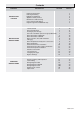
Contents CONTENTS INSTRUCTION FOR USE INSTALLATION INSTRUCTIONS SERVICING INSTRUCTIONS DESCRIPTION SECTION Important Information Draining and Filling Appliance Introduction Appliance Safety Devices Maintenance and Servicing User Controls and Lighting Digital Programmer F30E/F35E only PAGE No.
Important Information Gas safety (Installation and use) Regulations All external wiring between the appliance and the electrical supply and earthing requirements shall comply with the current IEE Regulations. In your interests and that of gas safety, it is the law that ALL gas appliances are installed and serviced by a competent person in accordance with the regulations. Connection of the boiler and system controls to the mains supply must be through a common isolator and must be fused at 3A, maximum.
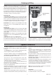
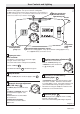
Draining and Filling 9744 Caution: The boiler is installed as part of a sealed system which must only be drained and filled by a competent person. If the mains electricity and gas are to be turned off for any long periods during severe weather, it is recommended that the whole system, including the boiler, refer to diagram 1, should be drained to avoid the risk of freezing. Make sure that, if fitted, the immersion heater in the cylinder is switched off. If in doubt, consult your servicing company.
Appliance Safety Devices Air flow rate safety device Frost protection If the flue is obstructed, the built in safety system will turn the boiler OFF, the fan will continue to run. The boiler will be ready to operate when the fault has been cleared. The appliance has a built in frost protection device that protects the boiler from freezing.
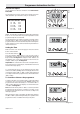
User Controls and Lighting The ECO setting is ideally suited for all the requirements of normal family use (showers, washing up etc.). The maximum setting should be reserved for occasional use when very hot water is required. 2 11443 Domestic hot water temperature selector (F30E/F35E Only) minimum setting approx. 38˚C up to maximum setting 60˚C. 5 Boiler ON indicator (fault indicated by light flashing red) On/Off switch 1 6 4 Pressure gauge (bar) and temperature gauge (°C) 1.
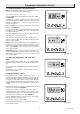
Programmer Instructions for Use 10205 General description The Programmer is fitted as standard to the Themaclassic F30E/F35E. The programmer is factory preset which switches the boiler “ON” and “OFF” up to three times a day as shown below. FACTORY PRESET TIMES 1st 1st 2nd 2nd 3rd 3rd ON OFF ON OFF ON OFF 6.30 8.30 12.00 12.00 16.30 22.30 Diagram 3 10302 NOTE: The 2nd “ON” and “OFF” preset time will not bring the boiler on.
Programmer Instructions for Use 10305 To set the programmer ON and OFF times Note: The programmer can be set to give a minimum of one and a maximum of three ON and three OFF times. Place the slide switch to “SET” (C1). Press the “enter” button. The display will show the first on time, see diagram 6. Using the + and - buttons, change the first on time to the time you require then press the “enter” button twice. This stores the new time and displays it to confirm it has been stored in the programmer memory.
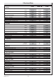
1 Technical Data F30E F30E SB F35E Heating Heat input (max) NET Q kW BTU/H 32,6 111,231 32,6 111,231 37,8 128,973 Heat input (min) NET Q kW BTU/H kW BTU/H kW BTU/H % °C litres bar litres bar 13,3 45,380 29,6 100,995 10,8 36,849 79,6 87 8 0,5 156 3 13,3 45,380 29,6 100,995 10,8 36,849 79,6 87 8 0,5 156 3 12 40,944 34,8 118,739 10,2 34,803 78,5 87 8 0,5 156 3 kW BTU/H 32,6 111,231 / / 37,8 128,973 kW BTU/H kW BTU/H kW BTU/H °C °C litres/min. litres/min.
658 1 Technical Data The Themaclassic F are delivered in two separate packages: • The boiler including hanging bracket complete with isolating valves and fittings. • The flue system 365 232 798 Net lift weight (boiler only) F30E 37 kg F30E SB 36 kg F35E 38 kg Gross lift weight (boiler, hanging bracket, isolating valves and packaging) F30E 41,5 kg F30E SB 40,5 kg F35E 43,5 kg 450 Diagram 2.1 2 General Information IMPORTANT NOTICE. The Water Fittings Regulations or Water Bylaws in Scotland.
2 General Information 2.3 Gas Supply Important Notice The gas installation must be in accordance with the relevant standards. If your boiler has been converted to use L.P.G. Propane the following note applies: In GB this is BS 6891. Propane cylinders are under pressure and should never be stored or used indoors residentially. In IE this is the current edition of I.S.813 "Domestic gas installation". They should only be kept outside. Under no circumstances should L.P.G.
3 Heating System Design 3.1 Bypass 3.3 Filling the system F30E SB •The boiler is fitted with an adjustable automatic bypass. Ensure that under no circumstances does the flow rate drop below the figure specified, see Table 1. • Provision for filling the system must be made. The methods are shown in diagram 3.2. There must be no permanent connection to the mains water supply, even through a nonreturn valve.
4 Domestic Hot Water System Design. F30E and F35E Only General - All domestic hot water circuits, connections, fittings must be in accordance with the relevant standards and water supply regulations. • The flow restrictor, supplied in the document envelope, must be fitted as diagram 7.1, limiting the flow through the boiler to a maximum of 12 litres/min for F 30 E and 14 litres/min for F 35 E. For GB: Guidance G17 to G24 and recommendation R17 to R24 of the Water Regulation Guide.
1 - Fan. 2 - Air pressure switch. 3 - Heat exchanger. 4 - Overheat thermostat. 5 - Combustion chamber. 6 - Expansion vessel. 7 - Flame sense electrode. 8 - Burner. 9 - Ignition electrode. 10 - Pump. 11 - Heating thermistor. 12 - Ignition unit. 13 - By-pass. 14 - Gas control valve. 15 - Loss of water sensor.
6 Boiler Location, Flue and Ventilation 6.1 Boiler Location The recommended clearances are shown in diagram 6.1. Note: The boiler must be mounted on a flat wall which is sufficiently robust to take its weight when full. If in doubt, expert advice should be obtained. The minimum acceptable spacings from the terminal to obstructions and ventilation openings are shown in diagram 6.2. For Ireland the minimum distances for the flue terminal positionning must be those detailed in I.S.
7 Fixing jig The fixing jig is made up as follows: A - Heating return fitting with isolating valve. B (F30E and F35E Only) - Cold water inlet fitting with isolating valve. The cold water inlet restrictor supplied with boiler is fitted when the boiler is installed. Refer to Section 9. C - Heating flow fitting with isolating valve. D (F30E and F35E Only) - Domestic hot water outlet. E - Gas service cock. Other components within the fixing jig pack.
8 Boiler Preparation and System Connections 8.1 Cutting the flue hole • Remove the wall template, follow the instructions given on the wall template. • Position the wall template, taking due regard of the minimum clearances for the selected flue application, see diagram 8.1. 63 • Horizontal Rear hole cutting 145 • Mark position of Rear flue outlet hole from template, then remove template, before cutting, for use, later. The core drill used should be 115 mm diameter.
9 Boiler Installation 9.1 Sheet metal parts WARNING: When installing or servicing this boiler, care should be taken when handling the edges of sheet metal parts to avoid the possibility of personal injury. 9.2 Installing the boiler IMPORTANT NOTE: The system must be thoroughly flushed using a propriety cleanser from Fernox or Sentinel to eliminate any foreign matter and contamination e.g. metal filings, solder particles, oil, grease etc. Solvent products could cause damage to the system.
The Horizontal Rear flue - kit No A2009700 is suitable for installations that require a flue length from 190mm minimum to 667mm maximum, without extensions, measurement taken from the rear of the boiler to outside wall face, see diagram 10.4 (3.). 10313a 10 Horizontal Rear Flue Installation A B G If a longer flue length is required a 1metre pipe extension can be used to give a maximum flue length of no more than 1500, measurement taken from the rear of the boiler to outside wall face.
RUBBER SEALING COLLAR PLASTIC INTERNAL FLANGE 40mm SELF ADHESIVE SEALS SAMPLE POINT SELF ADHESIVE GASKET 10234 10311 10 Horizontal Rear Flue Installation INNER WALL STANDARD FLUE ASSEMBLY ADAPTOR INNER WALL (1.) STANDARD FLUE ASSEMBLY Diagram 10.5 (2.) 10316 PLASTIC INTERNAL FLANGE RESTRICTOR (F30E/F30E SB only) SELF ADHESIVE SEALS FAN MINIMUM FLUE LENGTH 190mm MAXIMUM FLUE LENGTH 667mm 75mm MIN. 115mm 552mm MAX. 10315 Outside wall face Diagram 10.
10 Horizontal Rear Flue Installation 9741 Preparing the boiler • Lift the boiler up and engage boiler upper part onto the hanging bracket. EARTH LEAD FAN RETAINING SCREWS • Fit the washers between the boiler pipes and the inlet and outlet fittings on the fixing jig and connect the various couplings between the boiler and jig. Now the boiler is on the wall, slide forward the adaptor about 20mm. secure it on to the back of the boiler with the two screws supplied in the fittings kit, see diagram 10.7.
The Horizontal Telescopic Top Flue, Kit No. A2004500 11886a 11 Horizontal Telescopic Top Flue Installation SIDE FLUE Suitable for installations that require a flue length "L" from 430 minimum to 660 maximum. If longer flueing is required extensions and bends are available, see note below. L If the flue length, see diagram 11.2. is less than 430 'L' Do Not cut this flue but use the horizontal top flue 86285. 70mm Note: Additional 1 metre extensions, 90° and 45° bends are available.
11 Horizontal Telescopic Top Flue Installation 11879 11.3 Installation of telescopic flue assembly STEP 1. • For flue lengths less than 0.5m fit the restrictor (supplied in the document envelope) inside the fan outlet (F30E/F30E SB Only - see diagram 11.3) Outside wall face FLUE LENGTH • Remove the elbow (D) and the telescopic flue assembly (A) from the flue kit. 90mm (D) • Refer to Step 1. diagram 11.4. Fit the telescopic flue assembly (A) into the prepared hole in the wall.
12a.1 The Horizontal Top flue - kit 86285 11886 12 Horizontal Top Flue Installation SIDE FLUE Suitable for installations that require a max. flue length "L" of 740mm. If a shorter flue length is required, the flue can be cut to a min. length"L" of 260mm rear or 300mm side. See diagram 12a.2 for min. flue lengths. L 70mm 12a.2 Flue systems rear and side, refer to diagram 12a.1. 65mm 12a.3 Flue cutting, refer to diagram 12a.3.
12a.4 Installation of horizontal top flue assembly Outside wall face Important: If the flue has been cut, ensure that there are no burrs that could damage the ‘O’ ring. • For flue systems less than 0,5 m long, fit the flue restrictor (a) into the fan outlet, see diagram 10a.4. Flue centre line CL X 11643 12 Horizontal Top Flue Installation 90mm • Remove the backing from the self adhesive gasket (H) and carefully fit gasket to base of elbow (C).
13 Electrical Connection WARNING: This appliance must be earthed. This appliance must be wired in accordance with these instructions. Any fault arising from incorrect wiring cannot be put right under the terms of the Saunier Duval guarantee. 13.1 Mains Cable All system components must be of an approved type. 13.2 Voltage Free External Controls Electrical components have been tested to meet the equivalent requirements of the BEAB. Do not interrupt the mains supply with a time switch or programmer.
13 Electrical Connection 13.3 Mains Voltage External Controls WARNING: UNDER NO CIRCUMSTANCES MUST ANY MAINS VOLTAGE BE APPLIED TO ANY OF THE TERMINALS ON THE VOLTAGE FREE HEATING CONTROLS CONNECTION TERMINAL. STRAIN RELIEF When mains voltage external controls are used, remove the MAINS VOLTAGE HEATING CONTROLS CONNECTION PLUG from the fittings pack and install on the control interface PCB as follows.
14 Commissioning Important: The commissioning and first firing of the boiler must only be done by a competant person. Air in pipes Gas installation Important: A central heating system can not operate correctly unless it is filled with water and air bled from the system. If these conditions are not met the system may be noisy. If conversion from G20 to 30 or 31 is required, refer to section 15.
6. • Leave cap open on automatic air vent. 9810 5. • Bleed each radiator to remove air, ensure all bleed screws are re-tightened. • If necessary repressurise the system, refer to procedure 4 Ins 061a 14 Commissioning ➜ 8. • Open various hot water taps to bleed system 10217 Ins 062a 7. • Ensure the display indicates a system pressure of 1.0 bar adjust if necessary. 14.1 Adjusting the Central heating output. To gain access to potentiometer P3, unclip the control box, see diagram 13.3.
14 Commissioning 14.3 : Setting the flue parameters for Themaclassic F 35E This adjustment is made to ensure the boiler operates at maximum efficiency with longer flue lengths. Flue length for Themaclassic F 35 E Setting Horizontal flue (L) (C12) • Insert a small flat edge screw driver into the arrowed slot in potentiometer P7 (shown in diagram 14.2) : the code A will appear on the display A9 • Turn to adjust to the desired code according to the following table.
15 Changing Gas Type Should it be necessary to change the gas type, a conversion kit with instructions will be required. • Gain access to the gas control valve, connect a pressure gauge. This modification must only be carried out by a competent person. • Unclip the control box, see diagram 13.3. • Run the appliance in heating mode. Conversion natural gas (G20) to G30/G31 : • Read the burner pressure setting in heating mode, before the boiler modulates. Part No. A2011700 for F 30 E and F 30 E SB.
17 Routine Cleaning and Inspection 9532 REMEMBER, when replacing a part on this appliance, use only spare parts that you can be assured conform to the safety and performance specification that we require. Do not use reconditioned or copy parts that have not been clearly authorised by Hepworth Heating. PRODUCTS SAMPLING POINT To ensure the continued efficient and safe operation of the boiler it is recommended that it is checked and serviced at regular intervals.
17 Routine Cleaning and Inspection • Drain the boiler, refer to diagram 17.2. 9533 • On completion check all gas-carrying parts for soundness with leak detection fluid. 17.3 Front panel • Unscrew and remove the two retaining screws from the bottom of the front panel. • Remove front panel by lifting up and forward. 17.4 Control panel • Lower forwards to gain access to lower part of boiler. 17.5 Sealed chamber cover • Unscrew and remove the two retaining screws from the sealed chamber cover, see diagram.
17 Routine Cleaning and Inspection 17.7 Combustion chamber cover 17.14 Sealed chamber cover seal check • Unscrew and remove the two screws securing combustion chamber cover to combustion chamber, see diagram 17.5. Check the condition of the seal, replace as required. To replace remove the old seal, thoroughly clean the casing surfaces. Fit new seal, it supplied to the correct length, see diagram 20.25. • Remove combustion chamber cover from boiler. 17.8 Ignition and Flame Sensing Gaps 17.
9812a 9818a BURNER RETAINING SCREWS 9742 17 Routine Cleaning and Inspection BURNER GUIDE AIR PRESSURE SWITCH SENSING TUBE 9815a 9750 9817a FLUE HOOD Diagram 17.7 FAN RETAINING BOLTS EARTH LEAD CLIP DOMESTIC WATER INLET FILTER HOUSING POWER SUPPLY LEADS FILTER Diagram 17.8 Diagram 17.10 11935 F30E/F35 E Only 11934 F30E/F30E SB shown Diagram 17.9 9822 9741 HEAT EXCHANGER FLAT FILTER RETAINING CLIP F30E shown 4000123924-2 Diagram 17.
18 Fault Finding Before trying to operate the boiler make sure that : Overheat thermostat reset button • All gas supply cocks are open and that the gas supply has been purged of air. Refer to Section 20.10 to locate the overheat thermostat reset button. • The heating system pressure is at least 1 bar. Depress the button to reset. 9749 • There is a permanent mains supply to the boiler and that the polarity is correct. WARNING.
18 Fault Finding TYPE OF FAULT CHECK No display on control panel • 230V supply • PCB fuse • Connection between PCBs No domestic hot water (F30E/F35E Only) No central heating (Red flashing warning light and flashing fault code in display) • Loose connections on control board (PCB) • Connections on air pressure switch (electrical or tubes) disconnected • Faulty control or interface board (PCB's) • Water pressure, flashing pressure • Shortage of air or gas • Faulty temperature sensor • Overheating COMPON
18 Fault Finding FAULT: NO HEATING Are the external heating controls calling for heat? NO Rectify fault on external controls. YES Rectify, check the 230V controls board. NO Is the polarity correct? YES Connect 1 and 2 on J10, does boiler fire in central heating? NO Faulty main PCB. YES Faulty 230V controls board. F30E/F35E ONLY FAULT: NO HOT WATER, BUT THE HEATING IS WORKING Is the water pressure greater than 0.5 bar ? Insufficient water pressure. The appliance will not operate.
18 Fault Finding F1 FAULT DISPLAYED FAULT: THE BURNER LIGHTS BUT THEN GOES OUT. THERE IS NO FLAME DETECTED. The flame is not spreading across the whole burner and is not reaching the sensing electrode. Is the gas pressure correct? NO • Check that the gas taps are fully open • Check the gas pressure. YES • Clean the gas filter. • Clean the burner. F1 or F4 FAULT DISPLAYED FAULT: THE BURNER LIGHTS, THEN GOES OUT. The flame is spreading across the whole burner, but not being detected.
18 Fault Finding F1 FAULT DISPLAYED FAULT: THE BURNER DOES NOT LIGHT AT ALL, BUT THERE IS AN IGNITION SPARK. NO Are the gas taps on? Turn on the gas taps. YES Is there 24Vdc at the gas control valve? for testing see component testing data. NO YES Check the wiring. If the problem persists, change the control board (PCB). Test the gas control valve. Check resistance of safety valve coil. FAULT: THE ROOM TEMPERATURE IS INADEQUATE AND RADIATORS ARE LUKE-WARM.
18 Fault Finding F30E/F35E ONLY FAULT: THE WATER AT THE TAPS IS LUKE-WARM. Is the temperature higher if you reduce the flow through the taps? Check the 3-way valve is not passing into the radiators. (The radiators should stay cold in Summer setting) NO YES 11875 Check that the cold water inlet restrictor is fitted. Check the rate of flow. Check burner pressure is correct. FAULT: THE FAN DOES NOT START. Is there is 230V ac at fan during demand? NO Check continuity of fan harness.
g/y br b 3 1 w g IGNITION PLUG ELECTRODES IGNITOR UNIT SENSE ELECTRODE 3 4 w 1 GAS CONTROL VALVE OVERHEAT THERMOSTAT or bk AIR PRESSURE SWITCH FAN 2 PUMP g/y w THERMISTOR CH WATER PRESSURE SENSOR b bk bk CHASSIS EARTH w p y g or gn b w g g THREE-WAY VALVE MAINS VOLTAGE HEATING CONTROLS PLUG p w 230V SWITCHED LIVE FROM OPTIONAL FROST STAT. 230V SWITCHED LIVE FROM HEATING CONTROLS.
AIR PRESSURE SWITCH FAN g/y br b bk IGNITION ELECTRODES SENSE ELECTRODE 3 1 PLUG 3 w g or 4 w OVERHEAT THERMOSTAT w 2 PUMP CH bk THERMISTOR CH b 1 g/y bk WATER PRESSURE SENSOR IGNITOR UNIT GAS CONTROL VALVE CHASSIS EARTH w p y g or gn b w g MAINS VOLTAGE HEATING CONTROLS PLUG 230V SWITCHED LIVE FROM OPTIONAL FROST STAT. 230V SWITCHED LIVE FROM HEATING CONTROLS.
g/y br b 3 1 w g w FAN SENSOR 3 4 w 1 GAS CONTROL VALVE OVERHEAT THERMOSTAT or IGNITION PLUG ELECTRODES IGNITOR UNIT SENSE ELECTRODE p g bk AIR PRESSURE SWITCH FAN 2 PUMP g/y w THERMISTOR CH WATER PRESSURE SENSOR b bk bk CHASSIS EARTH w p y g or gn b w g g THREE-WAY VALVE MAINS VOLTAGE HEATING CONTROLS PLUG p w 230V SWITCHED LIVE FROM OPTIONAL FROST STAT. 230V SWITCHED LIVE FROM HEATING CONTROLS.
20 Replacement of Parts To Drain the central heating circuit • Open drain valve fitted at the lowest point in the system. • Allow air into the system by opening a radiator bleed screw or the boilers drain valve (f). (F30E/F35E Only) To Drain the Domestic hot water circuit • Close boiler isolating valve (b). • Turn on one or more hot water taps. To Drain the boiler • Close isolating screws on the isolating valves (a), (b) and (c). • Open the boiler drain valve (f).
20 Replacement of Parts 9646 20.2 Fan, refer to Section 17.10. Before starting refer to the front of Section 20 Important information. • Remove the front panel, refer to Section 17.3. • Remove the sealed chamber cover, refer to Section 17.5. • Remove the fan, refer to Section 17.10. RETAINING CLIPS AIR PRESSURE SWITCH 20.3 Air pressure switch Before starting refer to the front of Section 20 Important information. • Remove the front panel, refer to Section 17.3.
20 Replacement of Parts 9819 20.9 Burner injector assembly, refer to diagram 20.6. Before starting refer to the front of Section 20 Important information. • Remove the front panel, refer to Section 17.3. • Lower the control panel, refer to Section 17.4. • Remove the sealed chamber cover, refer to Section 17.5. • Remove the combustion chamber cover, refer to Section 17.7. • Remove burner from boiler, refer to Section 17.9. • Undo the gas supply union nut from under the sealed chamber.
20 Replacement of Parts • Remove the front panel, refer to Section 17.3. • Unclip control panel user interface and hinge forward . Do not strain the cables. • Disconnect the electrical connections from the user inter face board. • Remove the two user inter face board retaining screws. • Remove the user inter face board. 20.13 Heat exchanger, refer to diagram 20.7. Before starting refer to the front of Section 20 Important information. • Remove the front panel, refer to Section 17.3.
20 Replacement of Parts CONTROL BOARD COVER ➜ ➜ 10021 10020 PCB (CONTROL BOARD) Diagram 20.9 ➜ ➜ 10212 F30E shown 10219 CONTROL PANEL 230V CONTROLS BOARD MAINS SWITCH FOAM PACKING F30E shown 4000123924-2 50 ➜ USER INTERFACE BOARD PROGRAMMER (F30E/F35E Only) Diagram 20.
20.20 Central heating pump head, refer to diagram 20.11. Before starting refer to the front of Section 20 Important information. • Remove the front panel, refer to Section 17.3. • Lower the control panel, refer to Section 17.4. • Drain down central heating water circuit of the boiler only, refer to relevant part of diagram 20.1. Note: it is not necessary to drain down the entire heating system to carry out this work. • For ease of access if required remove the right hand side panel, refer to Section 17.6.
20 Replacement of Parts ➜ 9744 20.23 Boiler drain point, refer to diagram 20.13. Before starting refer to the front of Section 20 Important information. • Remove the front panel, refer to Section 17.3. • Lower the control panel, refer to Section 17.4. • Drain down the boiler only, refer to relevant part of diagram 20.1. Pull out slotted metal clip securing boiler drain valve into housing, remove boiler drain valve. BOILER DRAIN VALVE Diagram 20.13 ➜ ➜ 11590 ➜ ➜ ➜ 20.
20.26 Bypass valve, refer to diagram 16.1. Before starting refer to the front of Section 20 Important information. • Remove the front panel, refer to Section 17.3. • Lower the control panel, refer to Section 17.4. Drain down the boiler, refer to relevant part of Section 20.1. • Remove the igniter unit, refer to Section 20.33. Pull out slotted metal clip, ease out bypass valve from bypass valve housing. Please ensure that the new"O" ring and clip are fitted.
20 Replacement of Parts 11585 20.30 Discharge safety valve, refer to diagram 20.19. Before starting refer to the front of Section 20 Important information. • Remove the front panel, refer to Section 17.3. • Lower the control panel, refer to Section 17.4. • Drain down the boiler only. Refert to relevant part of diagram 20.1. • Undo discharge pipe union nut. • Pull out slotted metal clip from valve body and remove valve. ➜ ➜ PRESSURE RELIEF VALVE 20.
➜ ➜ ➜ 20.33 Ignition unit, refer to diagram 20.22. Before starting refer to the front of Section 20 Important information. • Remove the front panel, refer to Section 17.3. • Lower the control panel, refer to Section 17.4. • For ease of access remove the left hand side panel, refer to Section 17.6. • Disconnect electrical connections. • Remove ignition unit securing screw. • Pull upwards to release and remove the ignition unit from the retaining slot.
20 Replacement of Parts 20.35 Expansion vessel Renewal of the expansion vessel requires the boiler to be removed from the wall. As an alternative, a separate expansion vessel of the same specification may be connected as close as possible to the boiler, leaving the original in position, refer to the installation instructions. Replacing the expansion vessel Before starting refer to the front of Section 20 Important information. • For this operation the boiler must be removed from the wall.
20 Replacement of Parts • Remove the front panel, refer to Section 17.3. • Remove the sealed chamber cover, refer to Section 17.5. • Remove the old seal, thoroughly clean the casing. Fit the new seal, it is supplied to the correct length. Note: Ensure the seal is fitted correctly giving an air tight seal. SEALED CHAMBER COVER SEAL FRONT CASING PANEL 57 Diagram 20.
21 Spare parts When ordering spare parts, quote the part number and description, stating the appliance model number and serial number from the data badge. Short parts list No.
4000123924-2
Because of our constant endeavour for improvement details may vary slightly from those in the instructions.