
Instruction Manual


60 SawStop 10” Industrial Cabinet Saw
Making Adjustments to Your Saw
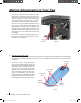
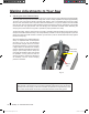
The head of the bolt is painted yellow for easy
identication. To adjust the position of the 45° limit
bolt, rst loosen the locking nut and back it off
several turns. Next, turn the 45° limit bolt clockwise
to increase the angle of the limit stop, or counter-
clockwise to decrease the angle of the limit stop.
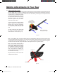
Now turn the tilt hand wheel clockwise until the
limit stop is reached. Recheck the angle of the
blade relative to the table. If further adjustment is
needed, decrease the tilt angle to about 30° and
readjust the 45° limit bolt. Repeat this process until
the blade is at 45° to the table when the limit stop
is engaged.
Once the 45° limit bolt is properly adjusted, turn
the locking nut clockwise until it is tight. The 45°
limit stop has now been set.
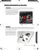
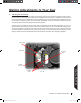
6. Adjusting the Table Insert:
The SawStop zero clearance insert has been designed to t securely within the table opening and just below
the table top. The insert is pre-cut at the factory with a 10 inch blade after all alignments to the saw have been
completed.
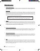
As shown in Fig. 67, the insert includes
front and rear leveling screws to set the
height of the insert. In addition, positioning
screws at the front and right side of the
insert prevent it from rattling in the table
opening. Finally, a lock-down screw at the
front of the insert prevents the insert from
rising up unexpectedly. The lock-down
screw ts inside an adjustable threaded
bushing that prevents the lock-down screw
from pulling the front of the insert too low.
Fig. 66
Fig. 67
45° tilt
limit stop
front leveling
screws
rear leveling
screws
positioning
screws
front lockdown
screw
threaded
bushing
Cabinet Saw Manual 1st Reprint.i60 60 3/9/2010 8:33:06 AM