SawStop ® OWNER’S MANUAL 10” INDUSTRIAL CABINET SAW Models ICS31230, ICS31240-50, ICS51230, ICS53230, ICS53415-50, ICS53480, ICS53600, ICS73230, ICS73480, ICS73600 Industrial Cabinet Saw Rev.
Copyright SawStop, LLC All Rights Reserved 3rd printing, October 2008 Interim Revision V3.4 (March 2010) Updates of this manual may be available at www.sawstop.com The saw shown on the front cover includes the optional 36 inch fence and extension table. Your saw may look different. SawStop, the SawStop blade logo, and the configuration of this product are either registered trademarks or trademarks of SawStop, LLC. Software copyright by SawStop, LLC. All rights reserved.
To Our Customers Thank you for purchasing a SawStop cabinet saw! It is the safest, most advanced table saw ever made. As you will soon discover, the features of the SawStop cabinet saw establish new standards in the table saw industry. Your saw includes our revolutionary, award-winning technology that can tell the difference between cutting wood and cutting a person.
Table of Contents Warranty 5 No Warranty of Safety 5 If You Have an Accident 5 Safety 6 WARNINGS 6 Warning Labels 8 The SawStop Safety System 10 Unpacking Your Saw 13 Get to Know Your Saw 14 Setting Up Your Saw 16 16 16 16 16 17 17 18 20 22 23 24 25 26 1. Saw Placement: 2. Extension Wing Assembly: 3. Table and Extension Wing Cleaning: 4. Rip Fence Installation: 5. Tilt Hand Wheel Handle Installation: 6. Blade or Dado Installation: 7. Brake Position Adjustment: 8.
Table of Contents 5. Using the Saw in Bypass Mode: 6. Using the Blade Guard: 7. Using the Riving Knife: 8. Using the Miter Gauge: 9. Cross-Cutting: 10. Rip Cutting: 11. Changing the Brake Cartridge: 33 34 35 35 37 38 40 What to do if the SawStop Safety System Activates 45 Making Adjustments to Your Saw 46 46 1. Aligning the Table: 10. Adjusting the Miter Gauge: 50 52 56 58 60 62 64 65 66 Cabinet Saw Specifications 67 Maintenance 68 68 68 68 68 68 2. Aligning the Blade Elevation Assembly: 3.
Table of Contents Push Block Construction 76 Auxiliary Fence Construction 77 Featherboard Construction 78 Electrical Schematics 230V, Single-Phase (3 and 5 HP): 240V, Single-Phase (3 HP): 230V, Three-Phase (5 and 7.5 HP): 415V, Three-Phase (5 HP): 480V, Three-Phase (5 and 7.5 HP): 600V, Three-Phase (5 and 7.
Warranty SawStop warrants to the original retail purchaser of a new industrial cabinet saw from an authorized SawStop distributor that the saw will be free from defects in material and workmanship for TWO YEARS from the date of purchase, and that the electric motor supplied with the saw will be free from defects in material and workmanship for FIVE YEARS from the date of purchase.
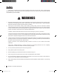
Safety A table saw is a dangerous tool and there are hazards inherent with using this saw. Some of these hazards are discussed below. Use common sense when operating the saw and use the saw only as instructed. You are responsible for your own safety! ! WARNINGS 1. Read and understand the instruction manual and all safety warnings before operating this saw. Failure to follow instructions or heed warnings may result in electric shock, fire, serious personal injury or property damage.
! WARNINGS 10. Do not try to force the saw to do something it was not designed to do. For example, do not try to cut wood faster than the motor can handle, and use the right blade for the job. 11. Wear proper apparel when using the saw. Do not wear loose clothing, gloves, neckties, rings, bracelets, or other jewelry which may get caught in moving parts. Non-slip footwear is recommended. Wear a protective hair covering to contain long hair. 12. Always wear safety glasses when using the saw.
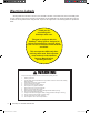
Warning Labels Warning labels are mounted on the front, rear and side of the saw, on the table insert, and on the blade guard for your reference. Some of the warnings on those labels may be additional to the warnings listed above. Be sure to read the warning labels before using the saw. Copies of the English text of the warning labels are reproduced below: Thank you for purchasing this SawStop® table saw.
! WARNING -OVING BELTS AND PARTS CAN PINCH CUT OR CRUSH ! WARNING 1. Use the blade guard and spreader for every operation for which it can be used. 2. Use the riving knife for non-through sawing. 3. Keep hands away from the saw blade. Use a push-stick when required. $O NOT OPERATE WITH DOOR OPEN ! ,OCKOUT BEFORE SERVICING WARNING To avoid loss of SawStop protection during coast down, do not turn off Main Power until blade has stopped spinning. (On saws with 230V, single phase motors.
The SawStop Safety System This table saw is equipped with the SawStop® safety system. This revolutionary technology was developed to reduce the potential for a serious injury in the event of accidental contact with the saw blade. SawStop® table saws are the first saws ever built to be smart enough to know the difference between you and the wood you are cutting. The SawStop® safety system includes two components, an electronic detection unit and a fast-acting brake.
The SawStop Safety System The SawStop® safety system does not interfere with your use of the table saw in any way. You can still make all the cuts that you can with ordinary saws including 0° to 45° bevels, non-through cuts, and dado cuts (with the optional dado brake cartridge—sold separately). Furthermore, no special blades or other accessories are required. Any standard 10 inch saw blade or 8 inch dado set is compatible with your SawStop® saw.
The SawStop Safety System 9. Never install the blade backwards. The brake might not stop a blade that is installed backwards, therefore you may receive a serious injury. 10. Blades with depth-limiting shoulders may take longer to stop in the event of an accident than standard blades, and you could receive a more serious injury. Therefore, SawStop recommends using blades without depthlimiting shoulders. 11. Never install two or more 10 inch blades together.
Unpacking Your Saw Use care when unpacking your saw to prevent damage to any of the saw components or accessories. Remove all packing materials and accessories before removing the saw from the shipping pallet. If the saw or the accessories have been damaged during shipping, report the damage to your shipper before proceeding with unpacking. Read and understand this manual fully before assembling and operating your saw. The package for your saw includes the following items: 1. One table saw with motor. 2.
Get to Know Your Saw The major components of your saw are identified below. Make sure you can identify these components in order to follow the instructions in this manual. 1 4 2 2 16 External Components 5 14 17 8 18 6 Fig. 2 3 11 15 12 10 1. Table Top 2. Extension Wings 3. Blade Guard 4. Standard Table Insert 5. Switch Box 6. Elevation Hand Wheel 7. Tilt Hand Wheel 8. Motor Cover 9. Terminal Box 10. Dust Port 11. Miter Gauge 12. Blade Wrenches (2) 13. Belt Access Door 14.
Get to Know Your Saw 33 21 27 28 40 39 22 20 Internal Components 37 41 32 31 38 Fig. 4 36 26 35 34 29 23 20. Front Trunnion Bracket 21. Front Trunnion 22. Rear Trunnion Bracket 23. Rear Trunnion 24. Elevation Plate 25. Motor 26. Arbor Block 27. Arbor Nut 28. Arbor Washer 29. Arbor Belt 30. Motor Belt 31. Dust Shroud Door 32. Upper Elevation Limit Bolt 33. Lower Elevation Limit Bolt 34. 0° Tilt Limit Bolt 35. 45° Tilt Limit Bolt 36.
Setting Up Your Saw 1. Saw Placement: Position the saw on a level surface away from sources of moisture and electrical noise. Make sure there is sufficient room to allow free access to all sides of the saw. If you plan to relocate the saw occasionally, mount the saw in the optional SawStop Industrial Mobile Base (see Fig. 6).
Setting Up Your Saw Setting Up Your Saw 5. Tilt Hand Wheel Handle Installation: Install the handle on the tilt hand wheel by screwing the threaded portion of the handle into the matching hole on the hand wheel (see Fig. 8). Use a wrench to tighten the handle securely to the hand wheel. handle tilt hand wheel Fig. 8 6. Blade or Dado Installation: WARNING! Only install standard 10 inch blades or 8 inch dado sets (with optional dado cartridge). Do not install other size blades or dado sets.
Setting Up Your Saw To install the blade, use the open end of one of the blade wrenches included with the saw to hold the arbor behind the arbor flange, and use the closed end of the other blade wrench to loosen the arbor nut. The arbor nut is right-hand threaded so turn the nut counter-clockwise to loosen it and clockwise to tighten it. After removing the arbor nut and arbor washer, install the blade and reinstall the arbor washer and arbor nut.
Note: some users may find it easier to adjust the brake position by opening the motor cover and removing the dust shroud door to see the blade and brake cartridge more clearly. To remove the dust shroud door, loosen the thumb screw and lift the door upward until the pivot pin in the door clears the pivot hole in the cast iron trunnion brace (see Fig. 11). Setting Up Your Saw Setting Up Your Saw thumb screw Fig.
Setting Up Your Saw A U.S. nickel can be placed between the closest points on the blade and brake cartridge to give a spacing of about 0.070 inch. The exact distance is not critical, but it is important to make sure the blade teeth do not touch the brake pawl. Note that the point on the brake pawl that is closest to the blade may be at the end of the brake pawl rather than the middle if the diameter of the blade is slightly less than 10 inches.
Note: when using a dado set, neither the blade guard nor the riving knife may be used. Instead, use other protective devices such as push sticks and featherboards. For the majority of cuts, the blade guard should be used. To install the blade guard, first remove the riving knife by lifting the clamping handle fully upward until the clamping plate moves away from the riving knife (see Fig. 14). Then move the riving knife slightly toward the right to clear the positioning pins, and lift it out of the clamp.
Setting Up Your Saw 9. Table Insert Installation: Your saw is shipped with a high-quality, zero-clearance table insert. The insert is factory-adjusted to fit securely in the table opening and below the table surface. If you wish to perform additional adjustment on the insert, see page 60 for instructions.
10. Connection of Dust Collection: Your SawStop® saw includes a dust shroud around the blade to provide superior dust collection to ordinary saws. A flexible hose connects the dust shroud to a 4 inch diameter dust port on the exterior of the cabinet (see Fig. 18). It is important to connect a suitable dust collection system to the dust port on the exterior of the cabinet. All table saws generate a substantial amount of dust, which can be a serious physical hazard.
Setting Up Your Saw 11. Electrical Power Connection: Your saw is shipped without a cord. The saw must be permanently connected to the building electrical system in accordance with the National Electrical Code and any other applicable state and local codes. Extension cords should not be used with this saw. Consult a licensed electrician if you are unsure how to properly connect the saw to the building electrical system.
Setting Up Your Saw Setting Up Your Saw 12. Disconnect Switch: The saw is equipped with an electrical disconnect switch mounted on the left side of the cabinet. When the disconnect switch is switched to OFF (see Fig. 20), electrical power is physically disconnected from the entire saw, including the SawStop safety system.
Setting Up Your Saw 13. Access Door Interlock Switches: As an additional safety feature, this saw is equipped with interlock switches on the belt access door and the motor cover that prevent the motor from starting when either door is open. In the event that one of the doors is opened while the motor is on, the corresponding interlock switch will cause the motor to shut down.
Using Your Saw 1. Adjusting the Blade Height: The height of the blade can be adjusted from 1/ 8 inch below the table top to 3 1/ 8 inch above the table top. To adjust the height of the blade, loosen the elevation locking knob and turn the elevation hand wheel until the blade is at the desired height (see Fig. 25). Turn the hand wheel clockwise to raise the blade, and counterclockwise to lower the blade. Lock the blade height by tightening the elevation locking knob.
Using Your Saw 3. Turning on Main Power and Starting the Motor: Your SawStop® saw is equipped with an Electrical Disconnect Switch to supply power to the saw, a Main Power Switch to supply power to the SawStop® safety system, and a Start/Stop paddle to turn the motor on and off. Both the Main Power Switch and the Start/Stop paddle are mounted on the Switch Box, which is located just below the front edge of the table and to the left of the elevation hand wheel (see Fig. 27).
Using Your Saw It is not necessary to turn off the Main Power switch after pushing in the Start/Stop paddle to turn off the motor. If you plan to make several cuts with the saw, you can leave the Main Power Switch in the ON position between cuts to eliminate the delay due to the initialization routine. Once you have finished using the saw turn the Main Power Switch to OFF to reduce the likelihood of inadvertent start-up.
Using Your Saw 4. System Status Codes: In the event that the safety system detects an error, the LEDs on the Switch Box will display a status code to indicate what error has been detected. Table 1 shows the different status codes which can be displayed. A complete description of each status code and the necessary corrective action is provided below.
Using Your Saw System Initializing — this code indicates that the system is performing self-checks and charging the brake system to fire in the case of an accident. This condition should clear within 15 seconds after the Main Power Switch is turned on. If the ambient temperature is very low (below about 0º F), this code may take longer to clear. The safety system detects such low temperatures within the brake cartridge.
Using Your Saw Contact was Detected During Standby — this code indicates that the safety system detected contact with the blade (or a portion of the arbor) when the blade was not spinning. This code will be displayed if you come into contact with the blade or arbor while the system is in Standby mode. The brake will not be activated and the code will automatically clear within 5 seconds after contact is ended. The system will not allow the motor to start while this code is displayed.
Using Your Saw 5. Using the Saw in Bypass Mode: If you need to cut electrically conductive materials such as aluminum with this saw, you must operate the saw in Bypass Mode to prevent the brake from activating. In order to operate the saw in Bypass Mode, the safety system requires you to follow the procedure below to ensure that the saw is never placed in Bypass Mode accidentally.
Using Your Saw 6. Using the Blade Guard: Using the blade guard is one of the most important steps you can take to prevent injury when using your saw. Most table saw injuries occur when the blade guard is either not being used or not being used properly. Your SawStop saw is equipped with a narrow profile blade guard that allows you to use the rip fence even when making narrow rip cuts. As a result, there are only a few situations where the blade guard cannot be used (e.g.
Using Your Saw 7. Using the Riving Knife: The riving knife should be used whenever the blade guard cannot be used. The only operation where neither the guard nor the riving knife can be used is making dado cuts. To use the riving knife, remove the blade guard and install the riving knife as described on page 20. When the blade guard / riving knife clamping bracket is properly aligned, the riving knife will be positioned below the top of the blade and inside the kerf of the blade.
Using Your Saw A guide plate is mounted on the end of the main bar (see Fig. 33) and fits in the bottom of the slots to hold the front of the miter gauge in place when the miter gauge head is positioned in front of the forward edge of the table. Three spring bearings are mounted in the side of the main bar to ensure the bar slides smoothly in the slots without excessive play.
Using Your Saw 9. Cross-Cutting: Cross-cutting or cutting perpendicular to the grain of the workpiece, is performed using the miter gauge. To lessen the risk of kickback, the rip fence should be removed or positioned so that it does not contact the workpiece during cross-cutting. Position the workpiece against the miter gauge head and slowly push the miter gauge toward the non-spinning blade until the workpiece is almost touching the blade.
Using Your Saw 10. Rip Cutting: Rip cutting or cutting with the grain of the workpiece must be performed with a rip fence to support and guide the workpiece. The miter gauge should not be used when making rip cuts. The blade guard should be used for all through cuts. To begin, make sure the motor is off and the blade is completely stopped. Tilt the blade to the desired tilt angle and adjust the blade elevation to about 1/ 8 inch above the workpiece.
Using Your Saw Continue pushing the workpiece toward the back of the saw until it clears the anti-kickback pawls on the spreader. Turn off the motor. Do not attempt to remove the cut-off portion until the blade has come to a complete stop. Fig. 37 When making non-through cuts, the blade guard and spreader must be removed. For these cuts, install the riving knife (except when making dado cuts) and use one or more featherboards to hold down the workpiece and help prevent kickback.
Using Your Saw 11. Changing the Brake Cartridge: The SawStop standard brake cartridge (shown in Fig. 39) includes a sealed housing containing the SawStop system electronics, and an aluminum block called a brake pawl. The sealed housing also includes a highspeed actuator that pushes the brake pawl into the teeth of the saw blade in the event accidental contact is detected. Like any electronic component, brake cartridges should be handled with care.
Using Your Saw WARNING! Never drop or otherwise subject a brake cartridge to misuse as this may damage the brake cartridge and potentially cause the brake pawl to be released unexpectedly and result in a serious injury. Changing the brake cartridge is both simple and foolproof. The safety system will not allow the motor to start unless the brake cartridge is correctly installed.
Using Your Saw You can change the brake cartridge either from the top of the saw through the table opening, or from the right side of the saw through the opening behind the motor cover. To change the cartridge from the right side, first open the motor cover. Next, remove the dust shroud door by loosening the thumb screw at the front of the door and lifting the door upward until the pivot pin clears the mounting shaft. See Fig. 11 on page 19.
Using Your Saw Fig. 44 You can remove the blade and brake cartridge simultaneously by alternately moving the blade and then the cartridge to the right to “walk” them off the arbor and pins. Often you can “walk” them to the right by hand, but if not, you can use a blade wrench as a lever. To do this, place one end of the wrench between the blade and the side of the arbor block as close to the arbor as possible. Then push the blade a short distance away from the arbor flange (see Fig. 45).
Using Your Saw Installing a Brake Cartridge: To install a brake cartridge, the above process is reversed. Align the mounting holes in the cartridge with the pivot pin and positioning pin in the saw. Push the cartridge onto the pins until it rests against the cartridge mounting bracket. The cartridge will automatically align with the computer cable mounted in the saw. Next, align the cartridge key with the hole in the cartridge housing. See Fig. 43.
What to do if the SawStop Safety System Activates When the SawStop Safety System is activated, the brake pawl will be pushed into the blade to stop its rotation. If the blade is spinning at a significant speed, the arbor block will retract to lower the blade below the table. Both of these actions will occur within just a few milliseconds. In addition, the safety system will turn off the motor, and display the “Replace Cartridge” system status code on the LED lights on the switch box (see page 30).
Making Adjustments to Your Saw Your SawStop saw has been factory adjusted to rigid specifications to provide the highest quality performance and results. Additional adjustment or alignment should not be necessary. Nevertheless, your SawStop cabinet saw has been designed to allow a wide range of adjustments and alignments to achieve the ultimate in precision. Before changing the alignment of any portion of the saw, make sure you read and understand the entire alignment procedure.
Making Adjustments to Your Saw Next, set the tilt angle to 0°. When setting the tilt angle and blade elevation, be sure to back the hand wheels off slightly after reaching the limit stops. As with all table saws, pulling the hand wheels tight against the limit stops can cause a slight twisting of the trunnion assembly and lead to inaccurate alignment measurements. Raise the blade elevation to about 3 inches above the table.
Making Adjustments to Your Saw The bolts that attach the table to the front trunnion bracket are shown below. The bolts that attach the table to the rear trunnion bracket (not shown) are at the back of the saw. To adjust the alignment, begin by loosening the 4 mounting bolts (see Fig. 49) that attach the table to the front and rear trunnion brackets using a 17 mm wrench or an adjustable wrench. Slide the dial indicator to the front of the blade and set the readout to zero.
Making Adjustments to Your Saw Alternate Table Alignment Procedure For this procedure you will need a set of calipers or a combination square. Begin by removing the table insert and installing a blade or reference plate as described in the Preferred Table Alignment Procedure. Set the tilt angle to 0º and raise the blade elevation to approximately 3 inches above the table. Select a point on the edge of the blade that is between two consecutive teeth and place a mark near that point.
Making Adjustments to Your Saw 2. Aligning the Blade Elevation Assembly: The blade elevation assembly controls the motion of the blade as it is raised and lowered. Aligning the blade elevation assembly ensures that there is minimal lateral movement of the blade as it is raised and lowered. Although all table saws suffer from some lateral blade movement due to tolerance stack-ups in machining, no other major cabinet saw allows you any adjustment to minimize this problem.
Making Adjustments to Your Saw This procedure requires two measurements. For the first measurement, set the tilt angle to 0° and lower the blade below the table. Make sure to back the hand wheels off slightly to release the pressure between the trunnion assembly and limit stops. Next, position the dial test indicator near the right side of the blade.
Making Adjustments to Your Saw Once the set screws are loosened, the eccentric bushing should be free to turn. Using a 22 mm open-end wrench or an adjustable wrench, turn the bushing in either direction while watching the dial test indicator reading. Turn the bushing as necessary until the reading is the same as the second measurement but in the opposite direction. For example, if the second measurement was +0.005 inch, then turn the eccentric bushing until the dial indicator reads -0.005 inch.
Making Adjustments to Your Saw The geometry involved in this alignment procedure is tricky. That is because there is no way to easily measure the parallelism between the blade and the tilt axis. Instead, you must measure the alignment between the blade and the table at both 0° tilt and 45° tilt. The difference in those measurements is proportional to the nonparallelism between the blade and the tilt axis. To ensure accurate alignment, follow the procedure described below exactly.
Making Adjustments to Your Saw To do this, set the tilt angle back to 0° and reposition the dial test indicator as described above. When you slide the dial indicator mount across the blade, you should see little or no change in the indicator readout since the table was previously aligned. Now, slide the dial indicator toward the rear of the saw until the measurement arm is about 1/ 2 inch inside the rear edge of the blade. Set the readout to zero.
Making Adjustments to Your Saw To create a positive misalignment, use a block of wood and a mallet to tap the left side of the elevation plate (see Fig. 60). To create a negative misalignment, use a block of wood and a mallet to tap the edges of the v‑bracket (see Fig. 61). tap here tap here Fig. 60 Fig. 61 Reposition the dial test indicator toward the front of the saw with the measurement arm about 1/ 2 inch inside the front edge of the blade. Set the dial readout to zero.
Making Adjustments to Your Saw 4. Adjusting the Elevation Limit Stops: The upper elevation limit stop prevents the arbor block and belts from hitting the underside of the table. The lower elevation limit stop prevents the arbor block or blade from hitting the lower trunnion assembly. The elevation limit stops must be adjusted correctly to ensure proper operation of the saw.
Making Adjustments to Your Saw Lower Elevation Limit Stop To check the position of the lower elevation limit stop, remove the blade from the arbor, open the motor cover, and remove the dust shroud door as described on page 19. While watching the arbor block through the motor cover opening, turn the elevation hand wheel counter-clockwise until the bottom of the arbor block just touches the rubber bumper mounted on the trunnion brace (see Fig. 63).
Making Adjustments to Your Saw 5. Adjusting the Tilt Limit Stops and Tilt Angle Indicator: The tilt limit stops allow you to easily and quickly set the bevel angle to 0° and 45°. However, when making precision cuts, it is always best to check the angle of the blade with a combination square or similar tool. 0° Tilt Limit Stop To check the position of the 0° limit stop, install a 10 inch saw blade on the arbor (see page 17).
Making Adjustments to Your Saw Tilt Angle Indicator The tilt angle indicator is located at the front of the cabinet, just behind the elevation hand wheel (see Fig. 66). The indicator shows the current angle of the blade relative to vertical (i.e., perpendicular to the table top). Once the 0° limit stop is correctly set, turn the tilt hand wheel counter-clockwise until the limit stop is reached. Check the reading of the tilt angle indicator.
Making Adjustments to Your Saw The head of the bolt is painted yellow for easy identification. To adjust the position of the 45° limit bolt, first loosen the locking nut and back it off several turns. Next, turn the 45° limit bolt clockwise to increase the angle of the limit stop, or counterclockwise to decrease the angle of the limit stop. Now turn the tilt hand wheel clockwise until the limit stop is reached. Recheck the angle of the blade relative to the table.
Making Adjustments to Your Saw To set the height of the insert, first remove the lock-down screw. Next, back off the threaded bushing by turning it counter-clockwise about one full turn using the included 5 mm hex L-wrench. Then use the included 3 mm hex L‑wrench to adjust the front and rear leveling screws until the insert is just below the surface of the table. The lower end of each leveling screw should rest on the corresponding support ledge on the table.
Making Adjustments to Your Saw 7. Aligning the Riving Knife and Spreader to the Blade: For safe operation, the spreader and riving knife should be aligned parallel to the blade, and positioned inside the kerf of the blade. The spreader, or alternatively, the riving knife, is held in position by a quick-release clamp mounted under the table and behind the blade (see Fig. 71). Once the clamp is properly adjusted, the spreader and riving knife will automatically align to the blade when installed in the clamp.
Making Adjustments to Your Saw WARNING! Make sure there is at least 3 mm spacing between the riving knife and blade at all points. Contact between the blade and either the riving knife or spreader during operation will cause the brake system to be activated. Remove the blade and set it aside for a moment. Tighten the horizontal positioning bolts. Remove the spreader and install the riving knife. Next, loosen the vertical positioning bolts using the included 5 mm hex L‑wrench.
Making Adjustments to Your Saw 8. Adjusting the Quick-Release Clamp: The clamping pressure of the spreader / riving knife quick-release clamp is factory adjusted to hold the spreader and riving knife securely when the handle is fully down. When correctly adjusted it will require approximately 10‑20 lbs. of force to push the handle to the fully down position. This is a moderate amount of force to apply with one hand.
Making Adjustments to Your Saw 9. Adjusting the Tilt Gearing: The tilt hand wheel changes the tilt angle of the blade by rotating a worm gear that engages a sector gear on the front trunnion. The worm gear should be fully engaged in the sector gear to eliminate any play in the tilt control mechanism. If the tilt angle does not begin changing as soon as the tilt hand wheel is turned, then it may be necessary to adjust the position of the worm gear.
Making Adjustments to Your Saw 10. Adjusting the Miter Gauge: The miter gauge bar includes three spring bearings which ensure a close fit between the miter gauge bar and the miter gauge slots in the table. The bearings can be adjusted to protrude further outward from the side of the bar to tighten the fit between the bar and the miter slots. Alternatively, the bearings can be adjusted inward to loosen the fit. To adjust the position of the spring bearings, insert a 2.
Cabinet Saw Specifications Overall saw dimensions: Cabinet footprint: Cast iron table: Extension wing: Extension table (optional): Weights (may vary with motor): Shipping weight (approx.): Blade: Blade diameter: Blade tilt: Blade kerf: Blade plate thickness: Max. depth of cut, blade at 0º: Max. depth of cut, blade at 45º: Max. rip, right of blade: Max. rip, left of blade: Dado diameter: Dado max. width: Arbor diameter at blade: Main bearing size: Second bearing size: Table in front of blade (max.
Maintenance 1. SawStop Safety System: The safety system in general requires little maintenance. The system performs continuous self-checks both before and during saw operation. If a problem is detected, the appropriate status code will be displayed on the LEDs on the switch box. Brake Cartridge: Although the brake cartridge requires no maintenance, the condition of the cartridge should be checked after approximately every 50 hours of saw use.
Troubleshooting Problem The motor will not start and both LEDs on the switch box are off. The motor will not start and at least one LED on the switch box is on. The motor stopped unexpectedly during use but the brake did not activate. The brake activated even though there was no accidental contact. Possible Cause(s) Solution 1. There is no power to the saw. 1. Ensure that the electrical supply to the saw is on and that the correct voltage is being supplied. 2.
Troubleshooting Problem Cannot turn saw on in Bypass mode. Possible Cause(s) Solution 1. The sequence for starting the saw in Bypass mode was not completed. 1. Follow the steps for starting the saw in Bypass mode exactly. 2. The safety system has detected a system error and is displaying an error code on the LEDs. 2. Consult the list of System Status Codes to determine the cause of the error and the corrective action. 3. The Bypass key is not fully seated. 3.
Troubleshooting Problem The blade slows down during cut, but does not stop. The blade hits the brake pawl during installation. The gears sound/feel rough when raising or lowering the blade. There is play in the tilt control so that the tilt hand wheel can be turned at least 1/ 8 revolution without changing the tilt angle of the blade. The saw does not make accurate 45° or 90° cuts. Possible Cause(s) Solution 1. One of the belts is not properly tensioned. 1.
Troubleshooting Problem The material binds when making a rip cut. The cuts are not even and/or clean. The saw vibrates too much. The motor starts slowly and/or fails to reach nominal speed. 72 Possible Cause(s) Solution 1. The rip fence is not aligned with the blade. 1. Align the fence to the blade. 2. The material is warped. 2. Select another piece of material. 3. The feed rate is too high. 3. Try again at a lower feed rate. 4. The spreader or riving knife is not aligned with the blade. 4.
SawStop 10” Industrial Cabinet Saw 73 Industrial Cabinet Saw Rev.
74 SawStop 10” Industrial Cabinet Saw Industrial Cabinet Saw Rev.
SawStop 10” Industrial Cabinet Saw 75 Industrial Cabinet Saw Rev. 2 Ma75 75 3/9/2010 8:39:06 AM 1/2" 1 1/2" This diagram illustrates a typical pushstick. Pushsticks should be constructed from material that is sturdy and electrically non-conductive such as scrap wood. Pushsticks should always be used when your hand comes within 6 inches of the blade. Squares are 1 inch. Pushstick should be 1/ 2 inch to 3/ 4 inch thick.
76 SawStop 10” Industrial Cabinet Saw Industrial Cabinet Saw Rev. 2 Ma76 76 3/9/2010 8:39:06 AM 9” 2" 1/2” B C B 5 1/4" (1/2” thick) 4 3/4" A 2" 9” A (3/4” thick) 3 1/2" 1/2" radius 5" 2" 2" This diagram illustrates a typical push block. It includes the three pieces shown here labeled A, B, and C. Cut piece A out of 3/ 4 inch plywood, and cut pieces B and C out of 1/ 2 thick plywood. Attach piece A to the center of piece B using wood glue and counter-sunk wood screws.
SawStop 10” Industrial Cabinet Saw 77 Industrial Cabinet Saw Rev. 2 Ma77 77 3/9/2010 8:39:06 AM B B A A (1/2” thick) (3/4” thick) 5 1/2” 2” To use the auxiliary fence, place it on the saw with piece B flat on the table top and piece A against the left side of the rip fence. Position the auxiliary fence so that the front edge of piece B is 1- 2 inches back from the front edge of the table, and then clamp piece A securely to the rip fence.
78 SawStop 10” Industrial Cabinet Saw Industrial Cabinet Saw Rev. 2 Ma78 78 3/9/2010 8:39:06 AM 60° 1/8" 1/4" 4" 1 inch squares. Featherboard should be approximately 3/ 4 inch thick. 7 3/4" This diagram illustrates a typical featherboard. Featherboards should be constructed from good quality wood that is free of knots. Use Featherboards to help keep the material being cut in contact with the table, and to help prevent kickback. Do not use featherboards when cutting with the miter gauge.
Electrical Schematic — 230V & 240V, Single-Phase (3 and 5 HP) ck Wh a Bl ite ck Bla DISCONNECT SWITCH Gre en White Green TERMINAL BOX ite k ac Bl Wh en Gre DO NOT USE* CONNECT EQUIPMENT GROUND HERE Black White CONNECT 208-240V 1-PHASE POWER HERE te Black hi W Black White Green Black 3L2 5L3 13NO 2T1 4T2 6T3 14NO White A2 COIL GROUND PLATE 1L1 NO COM NC BELT ACCESS DOOR INTERLOCK SWITCH Black A1 COIL Black White White 97 98 2T1 4T2 95 NO COM NC 96 6T
a Bl Wh ite ck Bla DISCONNECT SWITCH Gre en Red ck Red Electrical Schematic — 230V, Three-Phase (5 and 7.
Electrical Schematic — 415, Three-Phase (5 HP) a Bl Wh ite Red ck Bla DISCONNECT SWITCH Gre en Red ck White Green k ac Bl Red TERMINAL BOX ite Wh en Gre CONNECT 415V 3-PHASE POWER HERE Red FUSE e hit W Green Black k ac Bl White CONNECT EQUIPMENT GROUND HERE Black Red Red Black Black Black A1 COIL 1L1 3L2 5L3 13NO White A2 COIL 230V 2T1 4T2 6T3 415V NO COM NC BELT ACCESS DOOR INTERLOCK SWITCH 14NO 97 98 2T1 4T2 Bl ac Red Black White TRANSFORMER
Electrical Schematic — 480V, Three-Phase (5 and 7.
Electrical Schematic — 600V, Three-Phase (5 and 7.
84 SawStop 10” Industrial Cabinet Saw Industrial Cabinet Saw Rev. 2 Ma84 84 3/9/2010 8:39:07 AM ¯ ¯ SawStop ¯ ¯ ¯ ¯ ¯ ¯ ¯ ¯ •••••• •••••• •••••• Replace Cartridge System Ready System Initializing Status 68 ¯ ¯ ¯ •••••• ¯ Red System Status Codes Grn •••••• •••••• ¯ 52 59 ! 67 51 WAR To NING proteavoid do ction loss not durinof SawS bladeturn top off g has Maincoast stopp Powedown , ed spinnr until ing.
Cabinet and Table Assembly Parts List No. Description Part No. Qty. 1 Table CB104 001 1 2 Rear Lock Down Screw for Insert CB104 002 2 Extension Wing Assembly (complete) CB104 003 2 N/A 3 Cast Iron Wing CB104 004 2 4 M10x1.5x30 Hex Head Bolt CB104 005 6 5 M10.2x18.5 Lock Washers CB104 006 6 6 M10x25x3 Washers CB104 007 6 7 M10x1.
Cabinet and Table Assembly Parts List No. Description Part No. Contactor Box 3HP/208-240V/1-phase CB107 023 Contactor Box 5HP/208-240V/1-phase CB107 024 Contactor Box 5HP/208-240V/3-phase CB107 025 Contactor Box 5HP/480V/3-phase CB107 026 Contactor Box 7.5HP/208-240V/3-phase CB107 027 Contactor Box 7.5HP/480V/3-phase CB107 028 Contactor Box 5HP/600V/3-phase (Canada only) CB107 029 Contactor Box 7.
Cabinet and Table Assembly Parts List No. Description Part No.
88 SawStop 10” Industrial Cabinet Saw Industrial Cabinet Saw Rev.
Internal Assembly Parts List No. Description Part No. 3HP, 1PH, 208-240V, 60Hz, TEFC Motor CB104 069 5HP, 1PH, 208-240V, 60Hz, TEFC Motor CB104 071 5HP, 3PH, 208-240V, 60Hz, TEFC Motor CB104 072 5HP, 3PH, 480V, 60Hz, TEFC Motor CB104 073 7.5HP, 3PH, 208-240V, 60Hz, TEFC Motor CB105 015 7.5HP, 3PH, 480V, 60Hz, TEFC Motor CB105 016 5HP, 3PH, 600V, 60Hz, TEFC Motor (Canada only) CB107 054 7.
Internal Assembly Parts List No. 90 Description Part No. Qty. 31 M6x1.0x12 Socket Head Screw CB104 103 7 32 V-Bracket CB104 104 1 33 M8x1.25x20 Socket Head Screw CB104 105 4 34 M8.2x15.4 Lock Washer CB104 106 12 35 M5x0.8x15 Socket Head Screw CB104 107 4 36 M5.1x9.3 Lock Washer CB104 108 2 37 Elevation Plate CB104 109 1 38 Large Bronze Bushing CB104 110 2 39 M6.7x16x2 Washer CB104 111 4 40 Front Elevation Shaft CB104 112 1 41 M12x1.
Internal Assembly Parts List No. Description Part No. Qty. 73 Key CB104 145 2 74 Thrust Washer CB104 146 4 75 Collar CB104 147 2 76 5/16-18NC x 5/16 set screw CB104 148 4 77 Wave Washer CB104 149 1 78 Tilt Indicator CB104 150 1 79 M5.
92 SawStop 10” Industrial Cabinet Saw Industrial Cabinet Saw Rev.
Arbor Assembly Parts List No. Description Part No. Qty. 1 Arbor Block CB107 001 1 2 Arbor CB104 173 1 3 M5x5x28 Key CB104 174 1 4 Main Arbor Bearing CB104 175 1 5 Electrode Shell CB104 176 1 6 M4x0.
Arbor Assembly Parts List No. 94 Description Part No. Qty. 42 M4x0.7 Lock Nut CB107 019 2 43 Retraction Bracket CB104 214 1 44 Retraction Pawl CB104 215 1 45 M8x1.25x55 Hex Head Bolt CB104 216 1 46 Spring CB104 217 1 47 Sleeve CB104 218 1 48 M8x1.25x25 Hex Head Bolt CB104 219 1 49 M8.5x16x1 Washer CB104 220 1 50 Sleeve CB104 221 1 51 M10x1.5x25 Socket Head Bolt CB104 222 2 52 M10.2x18.
This page is blank. SawStop 10” Industrial Cabinet Saw 95 Industrial Cabinet Saw Rev.
96 SawStop 10” Industrial Cabinet Saw Industrial Cabinet Saw Rev. 2 Ma96 96 3/9/2010 8:39:09 AM WARNING 1. Use the blade guard and spreader for every operation for which it can be used. 2. Use the riving knife for non-through sawing. 3. Keep hands away from the saw blade. Use a push-stick when required.
Miter Gauge and Blade Guard Assemblies Parts List No. Description Part No. Qty. Blade Guard Assembly (complete) CB104 229 1 1 Guard Left Half CB104 230 1 2 Guard Right Half CB104 231 1 3 M3x1.06x8 Round Head Phillips Screw CB104 232 5 4 Pivot Arm CB104 233 1 5 Pivot Pin CB104 234 1 6 M6 E-Clip CB104 235 1 7 Splitter CB104 236 1 8 M6x1x35 Button Head Socket Screw CB104 237 1 9 M6.1x12.3 Lock Washer CB104 238 1 10 M6.
Accessories SawStop recommends the following accessories for use with your SawStop cabinet saw. Contact your local authorized SawStop Dealer or SawStop at 1-866-SAWSTOP for more information. 1.
Index A Accessories: 7, 11-13, 98 Accidental Contact: 10-12, 28, 31, 40, 44-45 Activation of Brake (see Brake Activation) Adjustments blade height: 27 blade tilt (bevel): 27, 37-38, 52-54, 58, 60, 62 brake position: 8, 18-19, 31, 44 limit stops elevation: 27, 51, 56-57 tilt: 27, 58-60 miter gauge: 36-37, 66 spreader and riving knife clamp: 64 table insert: 22, 60-61 tilt gearing: 65 Alignment blade elevation assembly: 27, 47-53, 55 riving knife and spreader: 20-21, 35, 62-63, 67 table: 27, 46, 48-49 t
Index Blade Guard anti-kickback pawl: 13, 34, 39, 62 guard: 7-8, 11, 13-14, 20-22, 25, 34-35, 38-39, 67, 98 spreader: 8, 13-15, 21-22, 34, 39, 41, 44, 62-64, 67 Brake activation: 10-12, 18, 22, 28, 31-33, 40, 45, 57, 63-64, 68 cartridge: 5, 7-8, 10-13, 15, 18-20, 31, 33, 40-45, 67-68, 98 cartridge key: 13, 15, 20, 31, 40, 42-44 dado (see Dado) changing the brake cartridge: 5, 8, 10, 18, 20, 31, 40-45, 68 pawl position adjustment: 8, 18-20, 31, 44 Brake Positioning Bolt: 15, 18, 43-44 Bypass key: 14, 24, 33
Index Dimensions: 73-74 Disconnect Switch: 7, 10, 14, 24-26, 28, 41, 45-46 Dust collection: 23, 67-68 hazard: 23 port: 14, 23, 67-68 Dust Shroud Door: 15, 19, 41-42, 44, 57 E Electrical grounding: 6, 24 power connection: 6, 8, 17, 24, 26 schematics: 79-83 Elevation changing the blade elevation: 18, 27, 37-38, 50 elevation handwheel: 13-14, 27-28, 45, 51, 56-59 elevation locking knob: 27 elevation plate: 15, 50-51, 55-57 elevation threaded rod: 15 limit stops: 27, 45, 51, 56-57 Exploded Views arbor assembly
Index I Insert (see Table Insert) Interlock Switch(es): 7, 26, 31 K Kerf: 21, 35, 62, 67 Kickback: 8, 20, 37, 39, 78 L LED(s): 26, 28, 30, 33, 44-45, 68 Limit Stop(s) elevation: 27, 45, 51, 56-57 tilt: 27, 58-60 Lock-Out: 29 M Main Power Switch: 7, 10, 12, 26, 28-32, 41, 45-46 Maintenance: 5, 25, 30, 68 Material Conductivity Test: 32 Miter Gauge adjustment: 36-37, 66 indexing pin: 36, 66 index stop(s): 36 slot(s): 14, 35-37, 46-49, 51-55, 66-67 spring bearings: 36, 66 use: 35-37 Mobile Base: 16, 98 Motor
Index R Rear Elevation Shaft: 50-51, 54 Rear Trunnion: 15, 48, 50, 52, 54-55 Rear Trunnion Bracket: 15, 48, 52 Retraction: 10, 12, 45, 57 Rip cutting: 34, 38-39, 46, 75 fence: 7, 16, 20, 34, 37-39, 46 narrow rip cuts: 34 Riving Knife: 13-15, 20-21, 25, 34-35, 39, 41, 44, 62-64, 67 S Saw Placement: 16 SawStop Safety System activation: 10-12, 18, 22, 28, 31-33, 40, 45, 57, 63-64, 68 bypass mode: 5, 7-8, 10-11, 13-14, 24, 31-33 operation: 5, 10-12, 17-18, 24-25, 28, 30-33, 41, 44-45, 68 system status codes(
Index Tilt angle: 14, 18, 27, 34, 37-38, 41, 47, 49, 51-54, 58-60, 62, 65 angle indicator: 14, 27, 58-59 angle scale: 14, 27 hand wheel: 13-14, 17, 27, 53, 58-60, 65 limit stop: 27, 58-60 locking knob: 27 TopCote®: 16, 68 TopSaver™: 16, 68 Troubleshooting: 69-72 Trunnion Brace: 19, 57 U Unpacking Your Saw: 13 Using Your Saw: 27-44 V V-bracket: 54-55 W Warning Labels: 8 Warranty: 1, 5, 12, 24 WD‑40®: 68 Wet Wood: 32 Wiring (see Electrical, power connection and schematic) Worm Gear: 65, 68 Z Zero-Cleara
Industrial Cabinet Saw Rev.
SawStop, LLC 9564 S.W. Tualatin Road Tualatin, Oregon 97062 www.sawstop.com phone 503-570-3200 fax 503-570-3303 email: info@sawstop.com March 2010 Industrial Cabinet Saw Rev.