SawStop ® Premium Fence Assembly OWNER’S MANUAL
Warranty SawStop warrants to the original retail purchaser of the Premium Fence Assembly from an authorized SawStop distributor that the fence system will be free from defects in material and workmanship for ONE YEAR from the date of purchase.
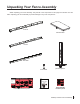
Unpacking Your Fence Assembly While unpacking your fence assembly, verify that all of the components on this page are included. Use care when unpacking your fence assembly to prevent damage to any of the components.
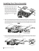
Installing Your Fence Assembly Note: Your saw must be fully assembled before installing the fence system. 1. Before you begin installing the Premium Fence Assembly, locate the front rail, the rear rail, and the fence assembly hardware pack (see Fig. 1). All of the hardware needed to install the fence system is located on the fence assembly hardware pack.
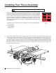
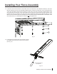
Installing Your Fence Assembly 3. Take two M8x1.25x25 flat head socket bolts and insert one through the open hole at the end of each extension wing, as shown in Fig. 3. 2 2 Fig. 3 4. Place an M8x23x2 washer and an M8 lock washer on the back of each of the M8x1.25x25 flat head socket bolts that extend through the extension wings, and then thread an M8x1.25 hex nut on each bolt (see Fig. 4). Hand tighten the nuts; do not fully tighten them.
Installing Your Fence Assembly 6. Take the rear rail (the smaller of the two rails) and align it to the rear edge of your saw by centering the notches in the rail with the two miter slots in the table and aligning the left-most hole between the notches with the corresponding hole in the rear edge of the table. There are three holes in the rail between the notches, one solitary hole and two holes paired together, and the left-most hole is the solitary hole.
Installing Your Fence Assembly 8. Use a straight-edge to level the rear edge of the left extension wing to the cast iron table top (see Fig. 8). You may have to pull up or push down on the outer edge of the extension wing to level it. Once the rear edge of the left extension wing is level, use a 5 mm hex key and a 13 mm wrench to fully tighten the nut on the bolt that mounts the left extension wing to the rear rail. Repeat this process to level the rear edge of the right extension wing.
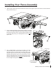
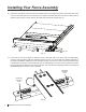
Installing Your Fence Assembly 10. The extension table mounts to the rails with bolts that pass through holes in the rails and extension table. Take four M8x1.25x25 flat head socket bolts and insert one bolt into each of the remaining holes in the front and rear rails. Place an M8x23x2 washer and an M8 lock washer on the back of each bolt and then thread an M8x1.25 hex nut on each bolt (see Fig. 10). Hand tighten the nuts; do not fully tighten them. 1 3 2 1 4 1 1 5 1 5 4 1 1 3 2 1 Fig. 10 11.
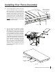
Installing Your Fence Assembly 13. Locate the main tube and remove seven M8x1.0x16 hex head bolts, seven M8x23x2 washers, and seven M8 lock washers from the fence assembly hardware pack. Position the main tube on the horizontal portion of the front rail with the rulers facing up and the 12 inch ruler on the left. The powder coated surfaces of the main tube and rail can be slick, so be careful that the main tube does not fall off the rail.
Installing Your Fence Assembly 15. The holes in the bottom of the front rail are oversized to allow you to adjust the position of the main tube on the rail. To set the main tube in the correct position, first pull the main tube away from the cast-iron table as far as possible. Next, place your fence down on the main tube near the left end (see Fig. 15). SawStop Fig. 15 main tube 16. Press down on the fence handle to clamp the fence to the main tube.
Installing Your Fence Assembly 17. Once the fence is tightly clamped to the main tube, move the left end of the main tube back toward the saw until there is only a small gap (approximately 1/16”) between the front rail and the rear face of the glide plate on the fence (see Fig. 17). Tighten the left-most M8x1.0x16 hex head bolt that holds the main tube to the front rail using a 13 mm wrench. Be careful not to overtighten the bolts because you may strip the threads in the main tube (recommended torque = 8.
Adjusting Your Rip Fence Although the fence is factory-adjusted to nominal settings, it is usually necessary to make final adjustments once your rails and extension table have been installed on the saw. The fence allows you to precisely set the width of your rip cuts (cuts that are length-wise along the grain of the wood). The precise width of cut is shown by the indicator lenses on the front of the fence (see Fig. 19).
Adjusting Your Rip Fence The next step is to align the face plates to be parallel to the miter slots. Begin by sliding the fence along the main tube until the left face plate is flush with the right edge of the right miter slot. Lock the fence handle and check that the face plate is flush with the miter slot edge along its whole length (see Fig. 21). You can check this either visually or by running your finger along the face plate and miter slot edge.
Adjusting Your Rip Fence You may find that after adjusting the face plates the end of the cross-bracket has been raised or lowered such that it is too close or too far away from the main tube. If this is the case, turn both plastic leveling screws the same amount in order to ensure the position indicator lenses are close, but not touching the front tube or rulers (see Fig. 24). Congratulations, your fence system is now installed and your saw is ready to use.
Using Your Rip Fence The rip fence included with your Premium Fence Assembly is used to guide material parallel to the blade when you make rip cuts (cuts that are length-wise along the grain of the wood). The fence must always be used when making rip cuts. To use the rip fence, begin by placing it on the table so that the fence glide bracket is resting on the upper rear edge of the main tube. You can use the fence on either the left or right side of the blade for non-bevel cuts.
Premium Rip Fence Exploded View 22 24 op t S w Sa 25 3 4 21 5 26 1 19 17 20 18 19 12 8 2 18 16 12 15 4 5 20 17 14 13 6 9 10 7 12 11 12 14 SawStop Premium Fence Assembly 27
Premium Rip Fence Parts List No. Description Part No. Qty. Premium Rip Fence (items 1-27) PFA-RF 1 1 Fence Tube PFA-001 1 2 Fence Head PFA-002 1 3 M6x1.0x12 Button Head Socket Bolt PFA-003 4 4 M6 Lock Washer PFA-004 6 5 M6x13x1.5 Washer PFA-005 6 6 Cam Lock PFA-006 1 7 Fence Handle PFA-007 1 8 M10x1.5x45 Hex Head Bolt PFA-008 1 9 M10x1.5 Lock Nut PFA-009 1 10 Flex Arm PFA-010 1 11 M5x0.
4 3 5 18 4 3 17 2 4 10 16 12 4 9 3 3 18 7 8 5 6 18 5 1 2 5 4 14 3 3 2 4 5 2 26 70 25 40 23 90 60 22 21 40 19 90 50 1 17 40 15 90 13 40 11 90 5 1 10 60 2 60 1 30 40 0 10 70 3 80 90 10 0 10 20 30 40 50 60 70 7 80 90 20 0 10 20 30 40 70 30 1F 10 20 50 50 20 10 13 3 6 7 70 60 9 20 14 1F300 90 80 60 1050 40 10 80 20 90 50 40 30 5 20 10 80 30 1 20 10 0 50 10 0 80 30 15 11 70 16 SawStop Premium Fence Assembly 4 90
Premium Rails and Extension Table Assembly Parts List No. Description Part No. Qty. 1 M8x1.25x16 Flat Head Socket Bolt PFA-029 8 2 M8x1.25x25 Flat Head Socket Bolt PFA-030 8 3 M8x23x2 Washer PFA-031 15 4 M8 Lock Washer PFA-032 15 5 M8x1.25 Hex Nut PFA-033 8 6 M6x1.0x32 Socket Head Shoulder Adjustment Bolt PFA-034 1 7 M9x18.3x2.3 Washer PFA-035 1 8 M9x12.5 Wave Washer PFA-036 1 9 M8 Retaining Ring PFA-037 1 10 M8x1.
SawStop, LLC 9564 S.W. Tualatin Road Tualatin, Oregon 97062 www.sawstop.com Main Phone - (503) 570-3200 Service - (503) 582-9934 Fax - (503) 570-3303 Email: info@sawstop.com Updates of this manual may be available at www.sawstop.com. Copyright SawStop, LLC. All Rights Reserved. SawStop is a registered trademark of SawStop, LLC.