
Assembly


Unpacking Your Fence Assembly
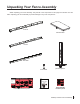
While unpacking your fence assembly, verify that all of the components on this page are included. Use care
when unpacking your fence assembly to prevent damage to any of the components.
main tube
front rail
rear rail
extension table
installation instructions poster
owner’s manual
fence handle
fence assembly
hardware pack
premium rip fence
1
0
9
0
1
0
2 0
3
0
4 0
5 0
0
6 0
7
0
8 0
9
0
1 0
2 0
3 0
4 0
5
0
6 0
7
0
8 0
20
9
0
1 0
2 0
3 0
4
0
5 0
6 0
7 0
8 0
30
9 0
1 0
2 0
3 0
4 0
5 0
6
0
7 0
8 0
40
0
9
0
1 0
2 0
3 0
4 0
5 0
6
0
7
0
8 0
5
0
0
9
0
1 0
2
0
3
0
4
0
5 0
6
0
7 0
8 0
6
0
0
9
0
1 0
2 0
3 0
4 0
5 0
6
0
7
0
8 0
70
0
1 0
2
0
3 0
4
0
5
0
6
0
0
1 0
2 0
3
0
4
0
5
0
6
0
7 0
8 0
9 0
10
0
1 0
2 0
3 0
4 0
5
0
6
0
7 0
8
0
9
0
20
0
1 0
2
0
3 0
4 0
5
0
6 0
7 0
8
0
9
0
30
0
SawStop
SawStop
®
OWNER’S MANUAL
Premium Fence Assembly
Fence Assembly Hardware Pack
2
Flat Head Socket Bolts,
M8x1.25x25 (8)
Flat Head Socket Bolts,
M8x1.25x16 (8)
1
Washers,
M8x23x2 (15 + 1 extra)
3
Lock Washers,
M8 (15 + 1 extra)
4
Hex Nuts,
M8x1.25 (8)
5
6
Hex Head Bolts,
M8x1.0x16 (7)
Installing Your SawStop Premium Fence Assembly
SawStop Service Department
503-582-9934
www.sawstop.com
© SawStop, LLC
4
9
3
2
1
8
5
6
7
Before assembling your Premium Fence
Assembly, make sure that you have all the
necessary components identified on page 1
in the owner’s manual, including the fence
assembly hardware pack. Call the SawStop
Service Department at 503-582-9934 if any
components are missing. You will also need
the following tools to complete the fence
assembly installation:
1. a 3 mm hex key
2. a 5 mm hex key
3. a 13 mm wrench
4. a straight-edge
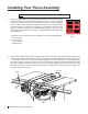
• Locate the front rail, the rear rail, and the fence assembly
hardware pack. All of the hardware needed to install the fence
system is located on the fence assembly hardware pack. In
order to easily identify the hardware used in each of the
following steps, the different pieces of hardware are numbered
on the hardware pack and in the figures.
Note: Your saw must be fully assembled before installing the
fence system.
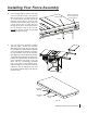
• Take the front rail (the larger of the two rails) and align it to
the front edge of your saw by centering the notches in the rail
with the two miter slots in the table and aligning the two holes
between the notches with the two corresponding holes in the
front edge of the table. Aligning the two holes between the
notches aligns all the other holes used in mounting the front
rail to your saw; different holes are used for different saws.
When the holes are aligned, mount the front rail to the saw by
taking four M8x1.25x16 flat head socket bolts and threading
one into each of the four threaded holes in the front edge of
the main table. Tighten the four bolts using a 5 mm hex key.
1
miter slots
1
front rail
notches
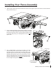
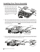
• Take two M8x1.25x25 flat head socket bolts and insert
one through the open hole at the end of each extension wing.
2
2
2
• Place an M8x23x2 washer and an M8 lock washer on
the back of each of the M8x1.25x25 flat head socket bolts
that extend through the extension wings, and then thread an
M8x1.25 hex nut on each bolt. Hand tighten the nuts; do
not fully tighten them.
3
4
2
5
SawStop
Sy
stem Stat
u
s
Codes
Stat
us
Red
G
rn
W
e
t
W
oo
d
Ove
rl
oa
d Due
To
Duri
ng
B
ypa
ss
Con
tact
Detec
t
e
d
Duri
n
g S
tand
by
Con
tact
Detect
e
d
Bra
ke
A
d
jus
t P
o
siti
o
n of
Doo
rs
Close
Acc
e
s
s
Key To
“On”
Turn
C
artr
idge
To “O
ff”
Tu
r
n S
tar
t S
wi
tch
Bypa
ss
Mod
e
On
Coa
sti
ng Do
w
n
Rep
lace
C
art
r
i
d
g
e
Syst
em
Rea
dy
Syst
em
Init
iali
zing
• • •
• • •
• • • • • •
• • •
• • •
• • • • • •
• • • •
• •
• • • • • •
• • • •
• •
2
3
4
5
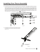
• Use a straight-edge to level the front edge of the left
extension wing to the cast iron table top. You may have to pull
up or push down on the outer edge of the extension wing to
level it. Once the front edge of the left extension wing is level,
use a 5 mm hex key and a 13 mm wrench to fully tighten the
nut on the bolt that mounts the left extension wing to the front
rail. Repeat this process to level the front edge of the right
extension wing.
straight-edge
level the extension
wing and tighten the
nut on this bolt
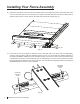
• Take the rear rail (the smaller of the two rails) and align it to
the rear edge of your saw by centering the notches in the rail
with the two miter slots in the table and aligning the left-most
hole between the notches with the corresponding hole in the
rear edge of the table. There are three holes in the rail
between the notches, one solitary hole and two holes paired
together, and the left-most hole is the solitary hole. Not all of
the holes are used to mount the rail to your saw; different
holes are used for different saws. Aligning the left-most hole
aligns all the other holes used in mounting the rear rail to your
saw. When the holes are aligned, mount the rear rail to the
saw by taking four M8x1.25x16 flat head socket bolts and
threading one into each of the four threaded holes in the rear
edge of the main table. Tighten the four bolts using a 5 mm
hex key.
!
W
A
R
NI
NG
M
ov
ing
g
e
a
rs
and
pa
rts
c
a
n p
inch,
cut or
crush.
Do
not
o
p
e
ra
te
w
it
h
doo
r
o
p
e
n.
align the left-most
hole between
the notches
1
1
!
WA
R
NIN
G
Movi
ng
ge
a
rs
a
nd pa
r
ts
ca
n
p
inc
h,
cu
t
or
c
r
us
h.
D
o not o
pe
r
at
e
with
door
ope
n.
• Take two M8x1.25x25 flat head socket bolts and insert
one through the open hole at the end of each extension wing.
Place an M8x23x2 washer and an M8 lock washer on
the back of each of bolt and then thread an M8x1.25 hex nut
on each bolt. Hand tighten the nuts; do not fully tighten them.
2
3
4
5
2
5
4
3
2
2
• Use a straight-edge to level the rear edge of the left
extension wing to the cast iron table top. You may have to pull
up or push down on the outer edge of the extension wing to
level it. Once the rear edge of the left extension wing is
level,
use a 5 mm hex key and a 13 mm wrench to fully
straight-edge
level the extension
wing and tighten the
nut on this bolt
Fence Assembly Hardware Pack
2
Flat Head Socket Bolts,
M8x1.25x25 (8)
Flat Head Socket Bolts,
M8x1.25x16 (8)
1
Washers,
M8x23x2 (15 + 1 extra)
3
Lock Washers,
M8 (15 + 1 extra)
4
Hex Nuts,
M8x1.25 (8)
5
6
Hex Head Bolts,
M8x1.0x16 (7)
• The next step of the assembly is easiest with two people.
Position the extension table between the front and rear rails.
Make sure that the table is oriented so that the adjustment
bracket is closest to the right extension wing. Tilt the extension
table slightly so that the adjustment bracket can fit under the
edge of the extension wing. Position the extension table so
that the end of the adjustment bolt aligns with the
corresponding threaded hole in the bottom of the extension
wing. With the weight of the extension table still supported,
turn the adjustment bolt until the extension table is roughly
flush with the extension wing.
adjustment
bolt
adjustment
bracket
adjustment
bracket
SawStop Premium Fence Assembly 1