
Assembly


2
5
4
3
SawStop
System Status Codes
Status
Red
Grn
¯
¯
¯
Wet Wood
Overload
Due To
During Bypass
Contact Detect
ed
During Standby
Contact Detected
Brake
Adjust Position
of
Doors
Close Acces
s
Key To “On”
Turn Cartri
dge
To “Off”
Turn Start
Switch
Bypass Mode O
n
Coasting Down
Replace Cartridge
System Ready
System Initiali
zing
• • • • • •
¯
¯
¯
¯
¯
¯
• • • • •
•
¯
¯
¯
• • • • • •
• • • • • •
• • • • • •
• • • • • •
¯
¯
¯
• • • • • •
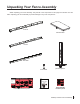
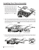
Installing Your Fence Assembly
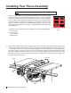
3. Take two M8x1.25x25 at head socket bolts and insert one through the open hole at the end of each extension
wing, as shown in Fig. 3.
Fig. 3
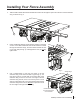
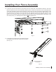
4. Place an M8x23x2 washer and an M8 lock washer on the back
of each of the M8x1.25x25 at head socket bolts that extend
through the extension wings, and then thread an M8x1.25 hex
nut on each bolt (see Fig. 4). Hand tighten the nuts; do not fully
tighten them.
Fig. 4
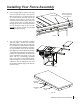
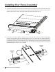
5. Use a straight-edge to level the front edge of the left
extension wing to the cast iron table top (see Fig. 5). You
may have to pull up or push down on the outer edge of the
extension wing to level it. Once the front edge of the left
extension wing is level, use a 5 mm hex key and a 13 mm
wrench to fully tighten the nut on the bolt that mounts the left
extension wing to the front rail. Repeat this process to level
the front edge of the right extension wing.
level the extension
wing and tighten the
nut on this bolt
straight-edge
Fig. 5
2
2
SawStop Premium Fence Assembly 3