SawStop ® T-Glide Fence SystemTM Professional Series OWNER’S MANUAL
Warranty SawStop warrants to the original retail purchaser of the T-Glide Fence System - Professional Series accompanying this manual that the fence system will be free from defects in material and workmanship for ONE YEAR from the date of purchase. This warranty does not apply to defects arising from misuse, abuse, negligence, accidents, normal wear-and-tear, unauthorized repair or alteration, or lack of maintenance. Please contact SawStop to take advantage of this warranty.
Unpacking Your T-Glide Fence System While unpacking your saw, verify that you have all the components shown below for your specific fence system. The T-Glide Fence System – Professional Series is available in either a 52” system or a 36” system. The components pictured below are from the 52” system, although the components from the 36” system are similar.
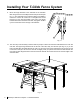
Installing Your T-Glide Fence System Note: Your contractor saw must be fully assembled before installing the fence system. Installing the Fence Rails 1. Locate the front rail, the rear rail, and the T-Glide rails hardware pack (see Fig. 1). All of the hardware needed to install the rails is located on the T-Glide rails hardware pack and is shipped in the T-Glide fence box.
Installing Your T-Glide Fence System 3. Place an M8.5 x 23 washer and an M8 lock washer on the back of each of the six M8 x 25 countersunk socket head bolts, and then thread an M8 hex nut on each bolt (see Fig. 3). Hand tighten the nuts; do not fully tighten them.
Installing Your T-Glide Fence System 6. Align the rear rail (the smaller of the two rails) with the rear edge of the table top so the cut-outs at the top of the rail are centered on the miter gauge slots in the table and so the holes in the rail align with the holes along the back edge of the table and extension wings. Notice that the holes in the table are threaded but the holes in the extension wings are not.
Installing Your T-Glide Fence System 8. Use a straight-edge to level the rear edge of the left extension wing to the cast iron table top (see Fig. 8). You may have to pull up or push down on the outer edge of the extension wing to level it. Once the rear edge of the left extension wing is level, use a 5 mm hex key and a 13 mm wrench to fully tighten the nut on the bolt that mounts the left extension wing to the rear rail. Repeat this process to level the rear edge of the right extension wing.
Installing Your T-Glide Fence System 11. Mount the angle brackets to the underside of the extension table using three M4 x 16 Phillips head screws per bracket (see Fig. 11). The underside of the extension table is pre-drilled to receive the screws. Be careful not to overtighten the screws because you may strip the threads in the wood. Once all the brackets have been mounted to the table, fully tighten the M10 nylon lock nuts that secure the legs to the brackets. 17 Fig. 11 12.
Installing Your T-Glide Fence System 13. Insert an M8 x 25 countersunk socket head bolt through each remaining hole in the front and rear rails and through the notches in the front and rear edges of the extension table. Place an M8.5 x 23 washer and an M8 lock washer on the back of each bolt and then thread an M8 hex nut on each bolt (see Fig. 13). Hand tighten the nuts; do not fully tighten them. 18 14 20 45 19 0 3 15 0 SawStopSaw actor 10” Contr Fig. 13 14.
Installing Your T-Glide Fence System 15. Repeat the process described in the previous step to level the rear edge of the extension table to the cast iron table top (see Fig. 15). straight-edge and the logo, blade registered LLC. are either the SawStop product of SawStop, LLC. SawStop, of this configuration or trademarks by SawStop, more of 2003-2006 by one or trademarks 6826988, copyright Software reserved. Protected6813983, 6945148, All rights U.S.
Installing Your T-Glide Fence System 17. Locate the front tube and the M8 x 16 hex head screws with attached washers from the T-Glide rails hardware pack. Position the tube on the horizontal portion of the front rail with the rulers facing up and the 12 inch ruler on the left side. The powder coated surfaces of the tube and rail can be slick, so be careful that the tube does not fall off the rail. Align the holes in the rail with the holes in the bottom of the tube.
Installing Your T-Glide Fence System 19. The holes in the bottom of the front rail are oversized to allow you to adjust the position of the tube on the rail. To set the tube in the correct position, first pull the front tube away from the cast-iron table as far as possible. Next, place your fence down on the tube near the left end (see Fig. 19). front tube Fig. 19 20. Press down on the fence handle to clamp the fence to the front tube.
Installing Your T-Glide Fence System 21. Once the fence is tightly clamped to the front tube, move the left end of the tube back toward the saw until there is only a small gap (approximately 1/16”) between the front rail and the rear of the fence (see Fig. 21). Tighten the left-most M8 x 16 hex head screw that holds the tube to the front rail using a 13 mm wrench. gap Fig. 21 22.
Using Your T-Glide Fence System The rip fence included with your T-Glide Fence System is used to guide material parallel to the blade when you make rip cuts (cuts that are length-wise along the grain of the wood). The fence must always be used when making rip cuts. The fence also allows you to precisely set the width of your rip cuts. To use the rip fence, begin by placing it on the table so that the fence glide bracket is resting on the upper rear edge of the front tube.
Adjusting Your T-Glide Fence System Although the fence is factory-adjusted to nominal settings, it is usually necessary to make final adjustments once your rails and extension table have been installed on the saw. The first step is to align the face plates to be parallel to the miter slots. Begin by sliding the fence along the front tube until the left face plate is flush with the right edge of the right miter slot.
Adjusting Your T-Glide Fence System If necessary, you can adjust both of the plastic leveling screws to ensure the position indicator lenses are close, but do not touch the front tube or rulers. The last step is to set the spacing between the bottom of each face plate and the table. The face plates are held in place by a series of screws threaded into nuts embedded in the face plates. The heads of the screws fit into key-hole slots in the sides of the fence (see Fig. 28). key-hole slot screw head Fig.
Adjusting Your T-Glide Fence System Once the left face plate has been removed, you can access the screws for the right face plate through the keyhole slots for the left face plate (see Fig. 30). Loosen each screw in the right face plate just enough to allow the face plate to slide against the fence, but tight enough so the face plate does not move freely.
16 SawStop T-Glide Fence System - Professional Series 11 10 7 1 2 9 3 4 12 17 18 25 18 4 3 2 10 18 8 6 23 17 24 1 15 19 13 14 21 20 17 22 14 22 5 1 17 16 14 20 18 19 17 24 Rails and Extension Table Exploded View for 52” Fence System
Rails and Extension Table Parts List for 52” Fence System No. Description Professional 52” T-Glide Fence Rails (items 1-12) Part No. Qty. TGP-R52A 1 M8x1.25x25 Countersunk Socket Head Bolt TGP-07-001 8 2 M8.5x23x2.0 Washer TGP-07-002 8 3 M8.2x15.4 Lock Washer TGP-07-003 8 4 M8x1.25 Hex Nut TGP-07-004 8 5 M8x1.25x16 Countersunk Socket Head Screw TGP-07-005 4 6 M8x1.
18 SawStop T-Glide Fence System - Professional Series 11 10 7 1 9 2 3 4 12 17 18 25 10 18 4 3 6 2 8 17 1 24 19 20 14 23 17 15 22 13 14 21 5 22 1 17 14 18 20 16 19 17 24 18 Rails and Extension Table Exploded View for 36” Fence System
Rails and Extension Table Parts List for 36” Fence System No. Description Professional 36” T-Glide Fence Rails (items 1-12) Part No. Qty. TGP-R36A 1 M8x1.25x25 Countersunk Socket Head Bolt TGP-07-001 8 2 M8.5x23x2.0 Washer TGP-07-002 8 3 M8.2x15.4 Lock Washer TGP-07-003 8 4 M8x1.25 Hex Nut TGP-07-004 8 5 M8x1.25x16 Countersunk Socket Head Screw TGP-07-005 4 6 M8x1.
20 SawStop T-Glide Fence System - Professional Series 3 6 10 9 8 11 12 15 10 14 13 4 5 7 10 16 2 11 10 S 1 aw 10 3 S 17 p o t T-Glide Fence Exploded View 2
T-Glide Fence Parts List No. Description Professional T-Glide Rip Fence Assembly (items 1-17) Part No. Qty. TGP-FA 1 1 Fence Tube TGP-07-036 1 2 Face Plate TGP-07-037 2 3 M6x1.0x12 Socket Head Screw TGP-07-038 20 4 Handle TGP-07-039 1 5 Cam Lock TGP-07-040 1 6 M10x1.5x50 Hex Head Bolt TGP-07-041 1 7 M10x1.5 Lock Nut TGP-07-042 1 8 Flex Plate TGP-07-043 1 9 Leveling Adjustment Screw M12x1.
SawStop, LLC 9564 S.W. Tualatin Road Tualatin, Oregon 97062 www.sawstop.com Main Phone - (503) 570-3200 Service - (503) 682-6222 Fax - (503) 570-3303 Email: info@sawstop.com Updates of this manual may be available at www.sawstop.com. Copyright SawStop, LLC. All Rights Reserved. SawStop is a registered trademark and T-Glide is a trademark of SawStop, LLC.