
Installation guide

WAFER-945GSE 3.5” Motherboard
Page 81
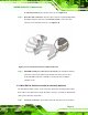
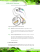
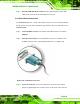
the WAFER-945GSE 40-pin serial port connector. See 810HFigure 5-16.
Step 3: Insert the cable connectors. Once the cable connector is properly aligned with
the 40-pin serial port connector on the WAFER-945GSE, connect the cable
connector to the on-board connectors. See
811HFigure 5-16.
Figure 5-12: Four Serial Port Connector Cable Connection
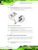
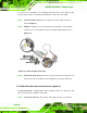
Step 4: Attach DB-9 serial port connectors to the chassis. The four DB-9 serial port
connectors can be inserted into four preformed holes in the chassis. Once,
inserted the DB-9 connectors should be secured to the chassis with the
retention screws.Step 0:
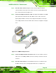
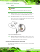
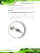
5.7.4 Dual RS-232 Cable Connection (w/o bracket) (Optional)
The dual RS-232 cable consists of two connectors attached to two independent cables.
Each cable is then attached to a D-sub 9-pin male connector. To install the dual RS-232
cable, please follow the steps below.
Step 1: Locate the connectors. The locations of the RS-232 connectors are shown in