
Installation guide

WAFER-945GSE 3.5” Motherboard
Page 83
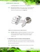
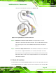
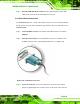
Step 2: Insert the cable connector. Align the cable connector with the onboard
connector. Make sure the pin 1on the cable connector is properly aligned with
pin 1 on the board connector.
812HFigure 5-14.
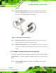
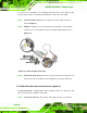
Step 3: Connect the adapter board to the cable. The adapter board with the four COM
ports must then be attached to the cable. Make sure the cable connector is
properly aligned with the connector on the adapter board. Make sure the pin 1
on the adapter board connector and the cable connector are aligned. See
813HFigure
5-14.
Figure 5-14: 4-COM Port Adapter Board
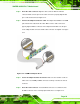
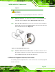
Step 4: Secure the adapter board to the chassis. Make sure the retention screws on
either side of each COM port DB-9 connector are firmly secured to the chassis
enclosure.
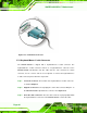
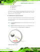
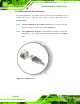
Step 5: Insert the serial connector. Insert the DB-9 connector of a serial device into
the DB-9 connector on the external peripheral interface. See
814HFigure 5-15.