
Installation guide

WAFER-945GSE 3.5” Motherboard
Page 85
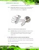
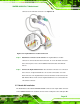
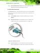
connector to the on-board connectors. See 816HFigure 5-16.
Figure 5-16: Keyboard/mouse Y-cable Connection
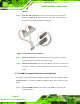
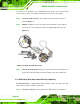
Step 4: Attach PS/2 connectors to the chassis. The keyboard/mouse Y-cable
connector is connected to two PS/2 connectors. To secure the PS/2 connectors
to the chassis please refer to the installation instructions that came with the
chassis.
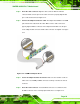
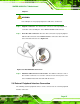
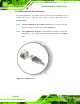
Step 5: Connect the keyboard and mouse. Once the PS/2 connectors are connected
to the chassis, a keyboard and mouse can each be connected to one of the
PS/2 connectors. The keyboard PS/2 connector and mouse PS/2 connector are
both marked. Please make sure the keyboard and mouse are connected to the
correct PS/2 connector. Step 0:
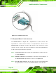
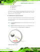
5.7.7 Audio Kit Installation
The Audio Kit that came with the WAFER-945GSE connects to the 10-pin audio connector
on the WAFER-945GSE. The audio kit consists of three audio jacks. One audio jack, Mic