
Installation guide

WAFER-945GSE 3.5” Motherboard
Page 87
Chapter 3.
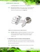
WARNING:
If the USB pins are not properly aligned, the USB device can burn out.
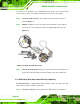
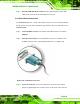
Step 2: Align the connectors. The cable has two connectors. Correctly align pin 1on
each cable connector with pin 1 on the WAFER-945GSE USB connector.
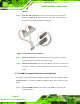
Step 3: Insert the cable connectors. Once the cable connectors are properly aligned
with the USB connectors on the WAFER-945GSE, connect the cable connectors
to the on-board connectors. See
818HFigure 5-18.
Figure 5-18: Dual USB Cable Connection
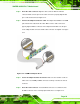
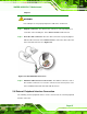
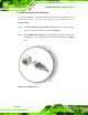
Step 4: Attach the USB connectors to the chassis. The USB 2.0 connectors each of
two retention screw holes. To secure the connectors to the chassis please refer
to the installation instructions that came with the chassis.Step 0:
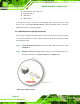
5.8 External Peripheral Interface Connection
The following external peripheral devices can be connected to the external peripheral
interface connectors.