
Installation guide

WAFER-945GSE 3.5” Motherboard
Page 89
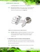
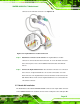
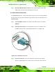
Step 3: Insert the LAN cable RJ-45 connector. Once aligned, gently insert the LAN
cable RJ-45 connector into the onboard RJ-45 connector. Step 0:
5.8.2 Serial Device Connection
The WAFER-945GSE has a single female DB-9 connector on the external peripheral
interface panel for a serial device. Follow the steps below to connect a serial device to the
WAFER-945GSE.
Step 1: Locate the DB-9 connector. The location of the DB-9 connector is shown in
Chapter 3.
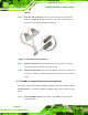
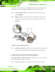
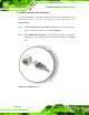
Step 2: Insert the serial connector. Insert the DB-9 connector of a serial device into
the DB-9 connector on the external peripheral interface. See
861H820HFigure 5-20.
Figure 5-20: Serial Device Connector
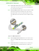
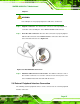
Step 3: Secure the connector. Secure the serial device connector to the external
interface by tightening the two retention screws on either side of the connector.
Step 0: