
Installation guide

WAFER-945GSE 3.5” Motherboard
Page 66
o When working with the WAFER-945GSE, make sure that it is
disconnected from all power supplies and that no electricity is being fed into
the system.
Before and during the installation of the WAFER-945GSE DO NOT:
Remove any of the stickers on the PCB board. These stickers are required for
warranty validation.
Use the product before verifying all the cables and power connectors are
properly connected.
Allow screws to come in contact with the PCB circuit, connector pins, or its
components.
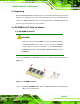
5.2.2 Installation Checklist
The following checklist is provided to ensure the WAFER-945GSE is properly installed.
All the items in the packing list are present
A compatible memory module is properly inserted into the slot
The CF Type I or CF Type II card is properly installed into the CF socket
The jumpers have been properly configured
The WAFER-945GSE is inserted into a chassis with adequate ventilation
The correct power supply is being used
The following devices are properly connected
o SATA drives
o Power supply
o USB cable
o Serial port cable
o Keyboard and mouse cable
The following external peripheral devices are properly connected to the
chassis:
o VGA screen
o USB devices