
Installation guide


WAFER-945GSE 3.5” Motherboard
Page 68
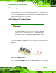
Step 2: Align the SO-DIMM with the socket. The SO-DIMM must be oriented in such a
way that the notch in the middle of the SO-DIMM must be aligned with the
plastic bridge in the socket.
Step 3: Insert the SO-DIMM. Push the SO-DIMM chip into the socket at an angle. (See
778HFigure 5-1)
Step 4: Open the SO-DIMM socket arms. Gently pull the arms of the SO-DIMM socket
out and push the rear of the SO-DIMM down. (See
779HFigure 5-1)
Step 5: Secure the SO-DIMM. Release the arms on the SO-DIMM socket. They clip into
place and secure the SO-DIMM in the socket.Step 0:
5.4.2 CF Card Installation
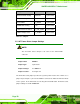
NOTE:
The WAFER-945GSE can support both CF Type I cards and CF Type
II cards. For the complete specifications of the supported CF cards
please refer to Chapter 2.
To install the a CF card (Type 1 or Type 2) onto the WAFER-945GSE, please follow the
steps below:
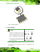
Step 1: Locate the CF card socket. Place the WAFER-945GSE on an anti-static pad
with the solder side facing up. Locate the CF card.
Step 2: Align the CF card. Make sure the CF card is properly aligned with the CF
socket.
Step 3: Insert the CF card. Gently insert the CF card into the socket making sure the
socket pins are properly inserted into the socket. See
780HFigure 5-2. Step 0: